How to Use 24V-5V 3A buck converter: Examples, Pinouts, and Specs
Introduction
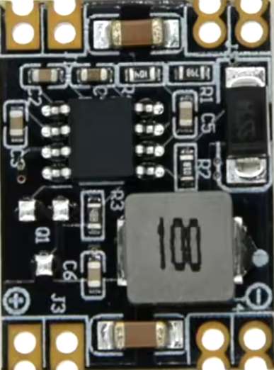
The 24V-5V 3A buck converter is a DC-DC step-down voltage regulator designed to convert a higher input voltage (24V) to a stable lower output voltage (5V) while delivering a maximum current of 3A. This component is highly efficient, minimizing energy loss during the conversion process. It is widely used in applications where devices operating at 5V need to be powered from a 24V source.
Explore Projects Built with 24V-5V 3A buck converter


Explore Projects Built with 24V-5V 3A buck converter
Common Applications and Use Cases
- Powering microcontrollers, such as Arduino boards, from a 24V power supply.
- Supplying 5V to USB-powered devices in industrial or automotive environments.
- Battery-powered systems requiring efficient voltage regulation.
- LED strips, sensors, and other low-voltage peripherals.
Technical Specifications
The following table outlines the key technical details of the 24V-5V 3A buck converter:
| Parameter | Value |
|---|---|
| Input Voltage Range | 6V to 24V |
| Output Voltage | 5V (fixed) |
| Maximum Output Current | 3A |
| Efficiency | Up to 95% |
| Switching Frequency | 150 kHz |
| Operating Temperature | -40°C to +85°C |
| Dimensions | Varies by model (e.g., 22mm x 17mm x 4mm) |
Pin Configuration and Descriptions
The buck converter typically has four pins or terminals. The table below describes each pin:
| Pin Name | Description |
|---|---|
| VIN | Input voltage pin (connect to 24V power source). |
| GND | Ground pin (common ground for input and output). |
| VOUT | Output voltage pin (provides regulated 5V output). |
| EN (optional) | Enable pin (used to turn the converter on/off). |
Note: Some models may not include an enable pin. Always refer to the specific datasheet for your buck converter.
Usage Instructions
How to Use the Component in a Circuit
Connect the Input Voltage (VIN):
Attach the VIN pin to a 24V DC power source. Ensure the input voltage is within the specified range (6V to 24V).Connect the Ground (GND):
Connect the GND pin to the ground of your circuit. This serves as the common reference point for both input and output.Connect the Output Voltage (VOUT):
Attach the VOUT pin to the device or circuit requiring a 5V power supply. Ensure the connected load does not exceed the maximum current rating of 3A.Optional - Enable Pin (EN):
If the buck converter includes an enable pin, connect it to a logic HIGH signal (e.g., 3.3V or 5V) to activate the converter. Pulling this pin LOW will disable the output.
Important Considerations and Best Practices
Heat Dissipation:
At high currents, the buck converter may generate heat. Use a heatsink or ensure proper ventilation to prevent overheating.Input Voltage Range:
Ensure the input voltage remains within the specified range (6V to 24V). Exceeding this range can damage the converter.Output Filtering:
Some buck converters include onboard capacitors for output filtering. If your circuit is sensitive to noise, consider adding additional capacitors (e.g., 100µF electrolytic and 0.1µF ceramic) near the load.Load Current:
Do not exceed the maximum output current of 3A. Overloading the converter can cause it to shut down or fail.
Example: Connecting to an Arduino UNO
The 24V-5V 3A buck converter can be used to power an Arduino UNO from a 24V power source. Below is an example circuit and Arduino code:
Circuit Connections
- Connect the VIN pin of the buck converter to the 24V power source.
- Connect the GND pin of the buck converter to the ground of the power source and the Arduino.
- Connect the VOUT pin of the buck converter to the 5V pin of the Arduino UNO.
Arduino Code Example
// Example code to blink an LED connected to pin 13 of the Arduino UNO
// Ensure the Arduino is powered via the 5V output of the buck converter

void setup() {
  pinMode(13, OUTPUT); // Set pin 13 as an output
}

void loop() {
  digitalWrite(13, HIGH); // Turn the LED on
  delay(1000);            // Wait for 1 second
  digitalWrite(13, LOW);  // Turn the LED off
  delay(1000);            // Wait for 1 second
}
Troubleshooting and FAQs
Common Issues and Solutions
No Output Voltage:
- Cause: The input voltage is too low or disconnected.
- Solution: Verify that the input voltage is within the specified range (6V to 24V).
Overheating:
- Cause: Excessive load current or poor ventilation.
- Solution: Reduce the load current or add a heatsink to the converter.
Output Voltage Fluctuations:
- Cause: Insufficient input or output filtering.
- Solution: Add capacitors (e.g., 100µF electrolytic and 0.1µF ceramic) to stabilize the voltage.
Converter Not Turning On:
- Cause: Enable pin is not connected or is pulled LOW.
- Solution: Connect the enable pin to a logic HIGH signal (if applicable).
FAQs
Q: Can I use this buck converter to power a Raspberry Pi?
A: Yes, as long as the Raspberry Pi's current requirements do not exceed 3A. Ensure proper heat dissipation for the converter.
Q: What happens if I exceed the maximum current rating?
A: The converter may shut down, overheat, or become permanently damaged. Always stay within the 3A limit.
Q: Can I adjust the output voltage?
A: No, this buck converter provides a fixed 5V output. For adjustable output, use a variable buck converter.
Q: Is reverse polarity protection included?
A: Most buck converters do not include reverse polarity protection. Use a diode in series with the input to prevent damage.