
How to Use OS4000-T: Examples, Pinouts, and Specs
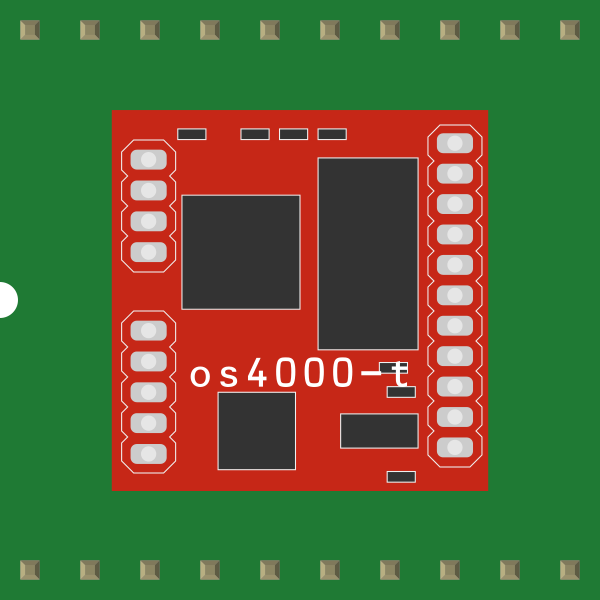
 Design with OS4000-T in Cirkit Designer
Introduction
The OS4000-T is a high-performance operational amplifier (op-amp) designed for precision signal processing applications. It offers low noise, high gain, and wide bandwidth, making it an ideal choice for a variety of analog circuits. This component is commonly used in instrumentation, audio processing, active filters, and precision amplifiers where signal integrity is critical.
Explore Projects Built with OS4000-T
 Open Project in Cirkit Designer
 Open Project in Cirkit Designer
 Open Project in Cirkit Designer
 Open Project in Cirkit Designer
Explore Projects Built with OS4000-T
Open Project in Cirkit DesignerOpen Project in Cirkit DesignerOpen Project in Cirkit DesignerOpen Project in Cirkit DesignerCommon Applications:
- Instrumentation amplifiers
- Audio preamplifiers
- Active filters
- Precision voltage followers
- Analog signal conditioning
Technical Specifications
The OS4000-T is engineered to deliver exceptional performance in demanding analog applications. Below are its key technical specifications:
| Parameter | Value |
|---|---|
| Supply Voltage Range | ±3V to ±18V |
| Input Offset Voltage | 0.5 mV (typical) |
| Input Bias Current | 10 nA (typical) |
| Gain Bandwidth Product | 10 MHz |
| Slew Rate | 5 V/µs |
| Input Noise Voltage | 4 nV/√Hz @ 1 kHz |
| Output Voltage Swing | ±(Vcc - 1.5V) |
| Operating Temperature | -40°C to +85°C |
| Package Options | DIP-8, SOIC-8 |
Pin Configuration
The OS4000-T is typically available in an 8-pin package. Below is the pinout and description:
| Pin Number | Pin Name | Description |
|---|---|---|
| 1 | Offset Null | Used for offset voltage adjustment |
| 2 | Inverting Input | Inverting input terminal (-) |
| 3 | Non-Inverting Input | Non-inverting input terminal (+) |
| 4 | V- (Negative Supply) | Negative power supply |
| 5 | Offset Null | Used for offset voltage adjustment |
| 6 | Output | Output terminal |
| 7 | V+ (Positive Supply) | Positive power supply |
| 8 | NC (No Connection) | Not connected internally |
Usage Instructions
The OS4000-T is versatile and can be used in a wide range of analog circuits. Below are guidelines for using the component effectively:
Basic Circuit Configuration
To use the OS4000-T as a basic amplifier:
- Connect the power supply to the V+ (pin 7) and V- (pin 4) terminals. Ensure the supply voltage is within the specified range (±3V to ±18V).
- Connect the input signal to the inverting (pin 2) or non-inverting (pin 3) input, depending on the desired configuration.
- Use appropriate feedback resistors to set the gain of the amplifier.
- Connect the output (pin 6) to the load or next stage of the circuit.
Important Considerations
- Power Supply Decoupling: Place decoupling capacitors (e.g., 0.1 µF ceramic and 10 µF electrolytic) close to the V+ and V- pins to minimize noise and ensure stable operation.
- Offset Adjustment: Use the offset null pins (pins 1 and 5) with a potentiometer to fine-tune the offset voltage if required.
- Thermal Management: Ensure the component operates within the specified temperature range (-40°C to +85°C) to avoid performance degradation.
Example: Connecting OS4000-T to an Arduino UNO
The OS4000-T can be used with an Arduino UNO for signal amplification. Below is an example of using the OS4000-T as a non-inverting amplifier to amplify an analog signal:
Circuit Setup:
- Connect the OS4000-T's V+ to +5V and V- to GND from the Arduino UNO.
- Connect the input signal to the non-inverting input (pin 3).
- Use a resistor network to set the gain (e.g., R1 = 10 kΩ, R2 = 100 kΩ for a gain of 11).
- Connect the output (pin 6) to an analog input pin on the Arduino (e.g., A0).
Arduino Code:
// OS4000-T Amplifier Example with Arduino UNO
// Reads an amplified analog signal and prints the value to the Serial Monitor

const int analogPin = A0; // Analog pin connected to OS4000-T output

void setup() {
  Serial.begin(9600); // Initialize serial communication at 9600 baud
}

void loop() {
  int sensorValue = analogRead(analogPin); // Read the amplified signal
  float voltage = sensorValue * (5.0 / 1023.0); // Convert to voltage
  Serial.print("Amplified Voltage: ");
  Serial.print(voltage);
  Serial.println(" V");
  delay(500); // Wait for 500 ms before the next reading
}
Notes:
- Ensure the input signal does not exceed the allowable input voltage range of the OS4000-T.
- Use proper grounding techniques to minimize noise in the circuit.
Troubleshooting and FAQs
Common Issues and Solutions
No Output Signal:
- Verify the power supply connections (V+ and V-).
- Check the input signal and ensure it is within the allowable range.
- Ensure the feedback network is correctly configured.
Output Signal is Distorted:
- Check if the input signal exceeds the op-amp's input voltage range.
- Verify that the power supply voltage is stable and within the specified range.
- Ensure proper decoupling capacitors are used near the power supply pins.
High Noise in Output:
- Use shielded cables for input signals to reduce interference.
- Add decoupling capacitors to the power supply lines.
- Minimize the length of PCB traces connected to the input pins.
Excessive Heat:
- Ensure the operating temperature is within the specified range.
- Check for short circuits or excessive current draw in the circuit.
FAQs
Q1: Can the OS4000-T be used for audio applications?
Yes, the OS4000-T's low noise and high gain make it suitable for audio preamplifiers and other audio processing circuits.
Q2: What is the maximum gain I can achieve with the OS4000-T?
The maximum gain depends on the feedback resistor configuration and the gain-bandwidth product (10 MHz). For high gains, ensure the bandwidth requirements of your application are met.
Q3: Can I use the OS4000-T with a single power supply?
Yes, the OS4000-T can operate with a single supply. However, you may need to bias the input signal appropriately to ensure proper operation.
Q4: How do I adjust the offset voltage?
Connect a potentiometer between the offset null pins (pins 1 and 5) and adjust it to minimize the output offset voltage.
By following these guidelines and best practices, you can effectively integrate the OS4000-T into your analog circuit designs.