How to Use TIVA: Examples, Pinouts, and Specs
Introduction
The TIVA family of microcontrollers, developed by Texas Instruments, is renowned for its high performance and low power consumption. These microcontrollers are widely used in embedded systems and Internet of Things (IoT) applications. They offer a robust set of features, including advanced connectivity options, extensive peripheral support, and efficient power management, making them ideal for a variety of applications ranging from industrial automation to consumer electronics.
Explore Projects Built with TIVA

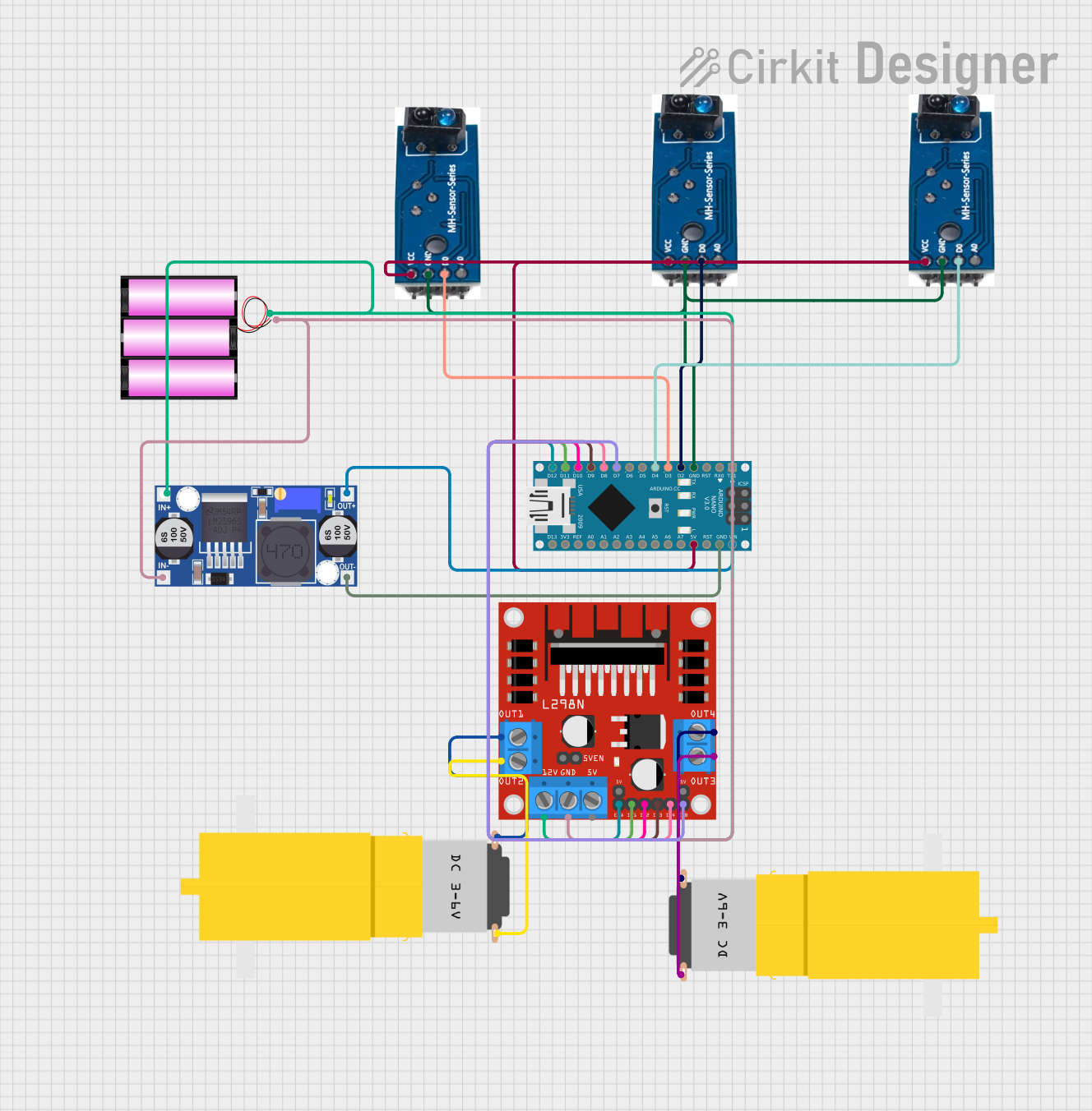
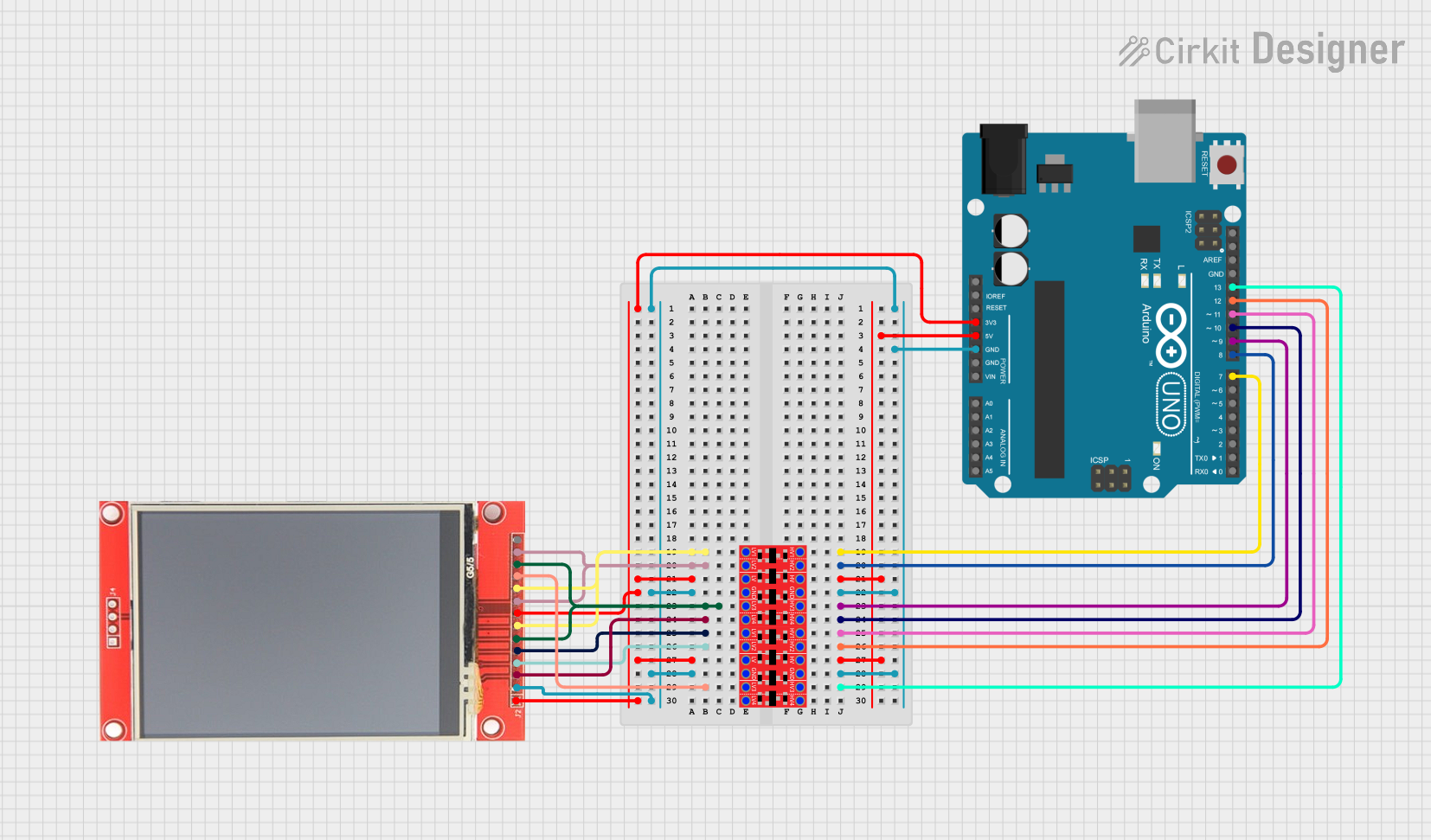
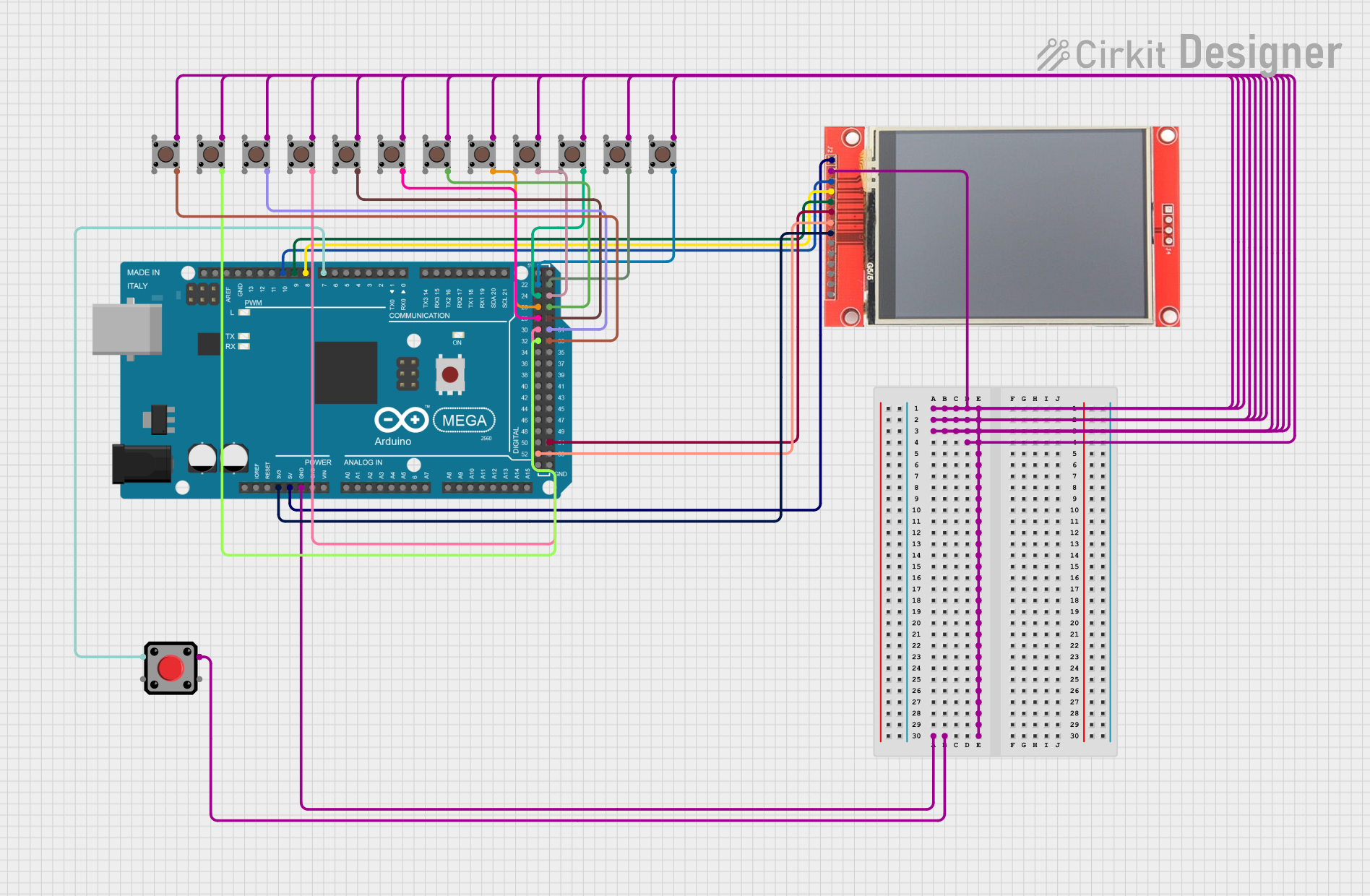
Explore Projects Built with TIVA
Technical Specifications
Key Technical Details
| Specification | Description |
|---|---|
| Core Architecture | ARM Cortex-M4 |
| Operating Voltage | 3.3V |
| Clock Speed | Up to 80 MHz |
| Flash Memory | Up to 1 MB |
| SRAM | Up to 256 KB |
| GPIO Pins | Up to 43 |
| Communication | UART, I2C, SPI, CAN, USB, Ethernet |
| ADC Channels | Up to 24 |
| Timers | Up to 12 |
| Power Consumption | Low power modes available |
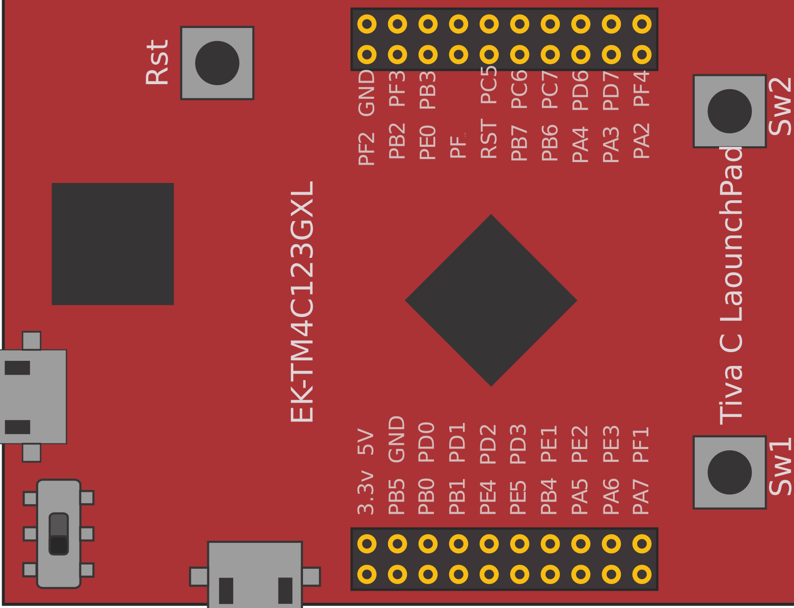
Pin Configuration and Descriptions
| Pin Number | Pin Name | Description |
|---|---|---|
| 1 | VDD | Power Supply (3.3V) |
| 2 | GND | Ground |
| 3 | PA0 | GPIO Port A Pin 0 / UART0 RX |
| 4 | PA1 | GPIO Port A Pin 1 / UART0 TX |
| 5 | PB0 | GPIO Port B Pin 0 / I2C0 SCL |
| 6 | PB1 | GPIO Port B Pin 1 / I2C0 SDA |
| ... | ... | ... |
| 43 | PC7 | GPIO Port C Pin 7 / USB0 D- |
Usage Instructions
How to Use the TIVA Microcontroller in a Circuit
- Power Supply: Connect the VDD pin to a 3.3V power source and the GND pin to the ground.
- GPIO Configuration: Configure the GPIO pins as needed for your application. For example, if you are using UART communication, connect the UART RX and TX pins to the corresponding pins on your peripheral device.
- Peripheral Initialization: Initialize the required peripherals (e.g., UART, I2C, SPI) in your firmware.
- Programming: Use an appropriate IDE (e.g., Code Composer Studio) to write and upload your code to the TIVA microcontroller.
Important Considerations and Best Practices
- Power Management: Utilize the low power modes to extend battery life in portable applications.
- Pin Multiplexing: Be aware of the pin multiplexing options and configure the pins correctly to avoid conflicts.
- Debouncing: Implement debouncing for mechanical switches to ensure reliable input readings.
- Firmware Updates: Regularly update the firmware to incorporate bug fixes and new features.
Example Code for Arduino UNO
// Example code to interface TIVA microcontroller with Arduino UNO
// This example demonstrates UART communication between TIVA and Arduino

#include <SoftwareSerial.h>

// Define RX and TX pins for SoftwareSerial
SoftwareSerial mySerial(10, 11); // RX, TX

void setup() {
  // Start the hardware serial communication
  Serial.begin(9600);
  // Start the software serial communication
  mySerial.begin(9600);
}

void loop() {
  // Check if data is available on the hardware serial port
  if (Serial.available()) {
    // Read the incoming byte
    char incomingByte = Serial.read();
    // Send the byte to the TIVA microcontroller
    mySerial.write(incomingByte);
  }

  // Check if data is available on the software serial port
  if (mySerial.available()) {
    // Read the incoming byte
    char incomingByte = mySerial.read();
    // Send the byte to the Arduino serial monitor
    Serial.write(incomingByte);
  }
}
Troubleshooting and FAQs
Common Issues
No Communication with Peripherals:
- Solution: Check the pin connections and ensure that the correct pins are used for the intended peripheral. Verify the initialization code for the peripheral.
Microcontroller Not Powering On:
- Solution: Ensure that the VDD pin is connected to a stable 3.3V power source and that the GND pin is properly grounded.
Unexpected Resets:
- Solution: Check for power supply stability. Ensure that the power supply can provide sufficient current. Look for any short circuits or loose connections.
FAQs
Can I use the TIVA microcontroller with a 5V power supply?
- No, the TIVA microcontroller operates at 3.3V. Using a 5V power supply can damage the microcontroller.
How do I program the TIVA microcontroller?
- You can use Code Composer Studio (CCS) or other compatible IDEs to write and upload code to the TIVA microcontroller.
What is the maximum clock speed of the TIVA microcontroller?
- The TIVA microcontroller can operate at a maximum clock speed of 80 MHz.
How do I configure the GPIO pins?
- GPIO pins can be configured using the appropriate registers in your firmware. Refer to the TIVA datasheet for detailed information on GPIO configuration.
By following this documentation, users can effectively utilize the TIVA microcontroller in their embedded systems and IoT applications. For more detailed information, refer to the official Texas Instruments documentation and datasheets.