Cirkit Designer
Your all-in-one circuit design IDE
Home /
Component Documentation
How to Use GY 91: Examples, Pinouts, and Specs
Introduction
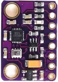
The GY-91 is a compact and versatile sensor module that integrates multiple sensors into a single board. It features a 3-axis accelerometer, a 3-axis gyroscope, and a 3-axis magnetometer, making it ideal for applications requiring motion tracking, orientation sensing, and environmental awareness. The module is based on the MPU-9250 (IMU) and BMP280 (barometric pressure sensor) chips, providing high precision and reliability.
Explore Projects Built with GY 91
Arduino UNO with A9G GSM/GPRS and Dual VL53L1X Distance Sensors

This circuit features an Arduino UNO microcontroller interfaced with an A9G GSM/GPRS+GPS/BDS module and two VL53L1X time-of-flight distance sensors. The A9G module is connected to the Arduino via serial communication for GPS and GSM functionalities, while both VL53L1X sensors are connected through I2C with shared SDA and SCL lines and individual SHUT pins for selective sensor activation. The Arduino is programmed to control these peripherals, although the specific functionality is not detailed in the provided code.
ADXL335 Accelerometer Data Visualization with Oscilloscope

This circuit connects an AITrip ADXL335 GY-61 accelerometer to an oscilloscope for signal visualization and a 3xAA battery pack for power. The accelerometer's Z-axis output is directly monitored on the oscilloscope, allowing for real-time observation of acceleration changes along that axis. The circuit is likely used for educational or testing purposes to demonstrate how the accelerometer responds to motion.
Arduino UNO and A9G GSM/GPRS GPS-Based Air Quality Monitoring System
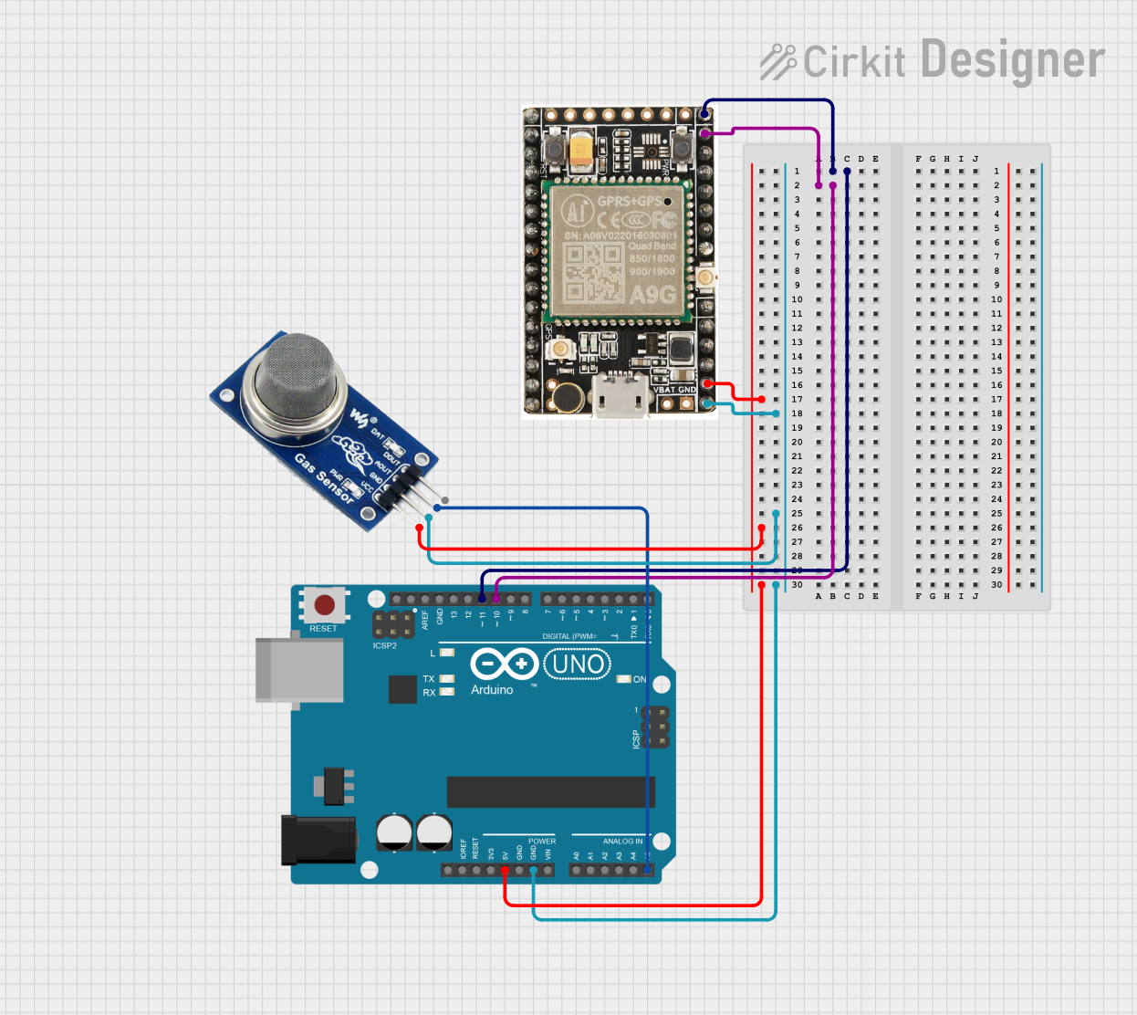
This circuit features an Arduino UNO microcontroller interfaced with an A9G GSM/GPRS+GPS module and an MQ2 gas sensor. The Arduino communicates with the A9G module via digital pins D11 and D10 for data transmission, and it reads analog gas concentration levels from the MQ2 sensor through analog pin A5. Both the A9G module and the MQ2 sensor are powered by the Arduino's 5V output, and all components share a common ground.
Arduino Nano-Based Multi-Zone Soil Moisture Monitor with OLED Display
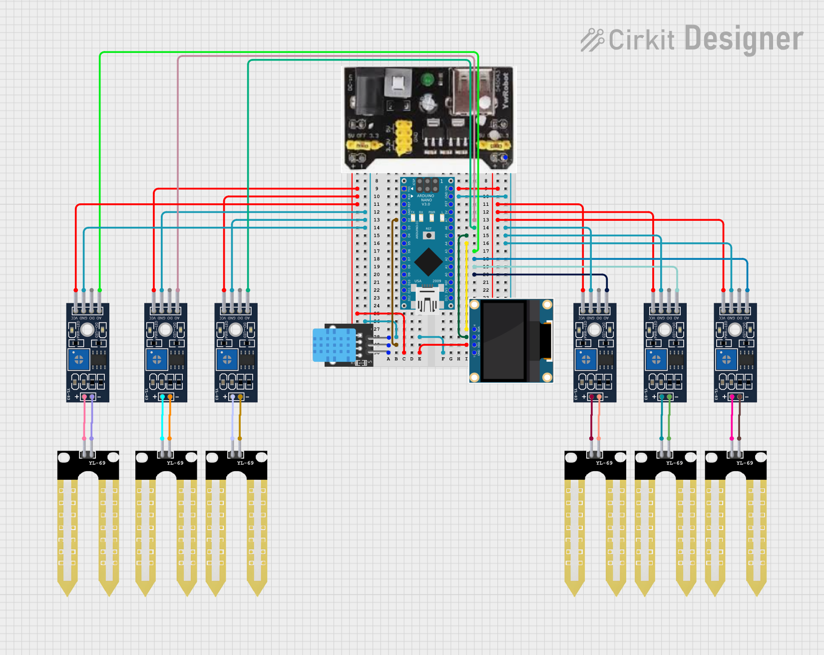
This circuit is designed to collect environmental data using multiple YL-83 modules with YL-69 sondas for soil moisture, and a KY-015 DHT11 sensor for humidity and temperature, all interfaced with an Arduino Nano. Data from the sensors is processed by the Arduino and displayed on an OLED screen, with power supplied by an MB102 Breadboard Power Supply Module.
Explore Projects Built with GY 91
Arduino UNO with A9G GSM/GPRS and Dual VL53L1X Distance Sensors
This circuit features an Arduino UNO microcontroller interfaced with an A9G GSM/GPRS+GPS/BDS module and two VL53L1X time-of-flight distance sensors. The A9G module is connected to the Arduino via serial communication for GPS and GSM functionalities, while both VL53L1X sensors are connected through I2C with shared SDA and SCL lines and individual SHUT pins for selective sensor activation. The Arduino is programmed to control these peripherals, although the specific functionality is not detailed in the provided code.
ADXL335 Accelerometer Data Visualization with Oscilloscope
This circuit connects an AITrip ADXL335 GY-61 accelerometer to an oscilloscope for signal visualization and a 3xAA battery pack for power. The accelerometer's Z-axis output is directly monitored on the oscilloscope, allowing for real-time observation of acceleration changes along that axis. The circuit is likely used for educational or testing purposes to demonstrate how the accelerometer responds to motion.
Arduino UNO and A9G GSM/GPRS GPS-Based Air Quality Monitoring System
This circuit features an Arduino UNO microcontroller interfaced with an A9G GSM/GPRS+GPS module and an MQ2 gas sensor. The Arduino communicates with the A9G module via digital pins D11 and D10 for data transmission, and it reads analog gas concentration levels from the MQ2 sensor through analog pin A5. Both the A9G module and the MQ2 sensor are powered by the Arduino's 5V output, and all components share a common ground.
Arduino Nano-Based Multi-Zone Soil Moisture Monitor with OLED Display
This circuit is designed to collect environmental data using multiple YL-83 modules with YL-69 sondas for soil moisture, and a KY-015 DHT11 sensor for humidity and temperature, all interfaced with an Arduino Nano. Data from the sensors is processed by the Arduino and displayed on an OLED screen, with power supplied by an MB102 Breadboard Power Supply Module.
Common Applications
- Robotics and autonomous vehicles
- Drones and UAVs for stabilization and navigation
- Mobile devices for motion detection and orientation
- Wearable devices for fitness tracking
- Gaming controllers and virtual reality systems
Technical Specifications
Key Technical Details
| Parameter | Value |
|---|---|
| Operating Voltage | 3.3V to 5V |
| Communication Interface | I2C, SPI |
| Accelerometer Range | ±2g, ±4g, ±8g, ±16g |
| Gyroscope Range | ±250°/s, ±500°/s, ±1000°/s, ±2000°/s |
| Magnetometer Range | ±4800 µT |
| Barometric Pressure Range | 300 hPa to 1100 hPa |
| Operating Temperature | -40°C to +85°C |
| Dimensions | 15mm x 15mm |
Pin Configuration and Descriptions
| Pin Name | Description |
|---|---|
| VCC | Power supply input (3.3V to 5V). |
| GND | Ground connection. |
| SCL | Serial Clock Line for I2C communication. |
| SDA | Serial Data Line for I2C communication. |
| CS | Chip Select for SPI communication (active low). |
| SDO | Serial Data Output for SPI communication. |
| INT | Interrupt pin for motion detection or data-ready signals. |
Usage Instructions
How to Use the GY-91 in a Circuit
- Power Supply: Connect the VCC pin to a 3.3V or 5V power source and the GND pin to ground.
- Communication Interface:
- For I2C: Connect the SCL and SDA pins to the corresponding I2C pins on your microcontroller.
- For SPI: Connect the CS, SDO, and SCL pins to the SPI interface of your microcontroller.
- Pull-Up Resistors: If using I2C, ensure pull-up resistors (typically 4.7kΩ) are connected to the SCL and SDA lines.
- Interrupt Pin: Optionally, connect the INT pin to a GPIO pin on your microcontroller to handle interrupts.
Important Considerations
- Ensure the operating voltage matches the microcontroller's logic level (3.3V or 5V).
- Use proper decoupling capacitors near the power supply pins to reduce noise.
- Avoid placing the module near strong magnetic fields or vibrations to maintain accuracy.
Example Code for Arduino UNO (I2C)
#include <Wire.h>
#include <Adafruit_Sensor.h>
#include <Adafruit_MPU6050.h>
#include <Adafruit_BMP280.h>

// Create instances for MPU6050 (IMU) and BMP280 (barometric sensor)
Adafruit_MPU6050 mpu;
Adafruit_BMP280 bmp;

void setup() {
  Serial.begin(115200);
  while (!Serial); // Wait for Serial Monitor to open

  // Initialize MPU6050
  if (!mpu.begin()) {
    Serial.println("Failed to find MPU6050 chip!");
    while (1);
  }
  Serial.println("MPU6050 initialized successfully!");

  // Initialize BMP280
  if (!bmp.begin(0x76)) { // Default I2C address for BMP280
    Serial.println("Failed to find BMP280 sensor!");
    while (1);
  }
  Serial.println("BMP280 initialized successfully!");
}

void loop() {
  // Read accelerometer and gyroscope data
  sensors_event_t a, g, temp;
  mpu.getEvent(&a, &g, &temp);

  // Print accelerometer data
  Serial.print("Accel X: "); Serial.print(a.acceleration.x); Serial.print(" m/s^2, ");
  Serial.print("Y: "); Serial.print(a.acceleration.y); Serial.print(" m/s^2, ");
  Serial.print("Z: "); Serial.print(a.acceleration.z); Serial.println(" m/s^2");

  // Print gyroscope data
  Serial.print("Gyro X: "); Serial.print(g.gyro.x); Serial.print(" rad/s, ");
  Serial.print("Y: "); Serial.print(g.gyro.y); Serial.print(" rad/s, ");
  Serial.print("Z: "); Serial.print(g.gyro.z); Serial.println(" rad/s");

  // Read and print barometric pressure
  Serial.print("Pressure: "); Serial.print(bmp.readPressure()); Serial.println(" Pa");

  // Delay for readability
  delay(1000);
}
Troubleshooting and FAQs
Common Issues
No Data from the Sensor:
- Ensure the wiring is correct and matches the selected communication protocol (I2C or SPI).
- Verify that the I2C address (default: 0x68 for MPU9250, 0x76 for BMP280) is correct in your code.
- Check for loose connections or damaged wires.
Inaccurate Readings:
- Calibrate the accelerometer, gyroscope, and magnetometer before use.
- Avoid placing the module near sources of electromagnetic interference.
Module Not Detected:
- Ensure pull-up resistors are present on the I2C lines.
- Confirm that the power supply voltage is within the specified range.
Tips for Troubleshooting
- Use an I2C scanner sketch to detect the module's address.
- Test the module with a different microcontroller to rule out hardware issues.
- Check the datasheets for MPU-9250 and BMP280 for advanced configuration options.
By following this documentation, you can effectively integrate the GY-91 sensor module into your projects and troubleshoot common issues with ease.