How to Use RDM 6300: Examples, Pinouts, and Specs
Introduction
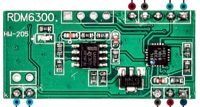
The RDM 6300 is a Radio Frequency Identification (RFID) reader module designed to read passive RFID tags operating at a frequency of 125 kHz. It is commonly used in applications such as access control, identification, tracking of goods and livestock, and user authentication. The module interfaces with microcontrollers such as the Arduino UNO and can be easily integrated into various electronic projects.
Explore Projects Built with RDM 6300

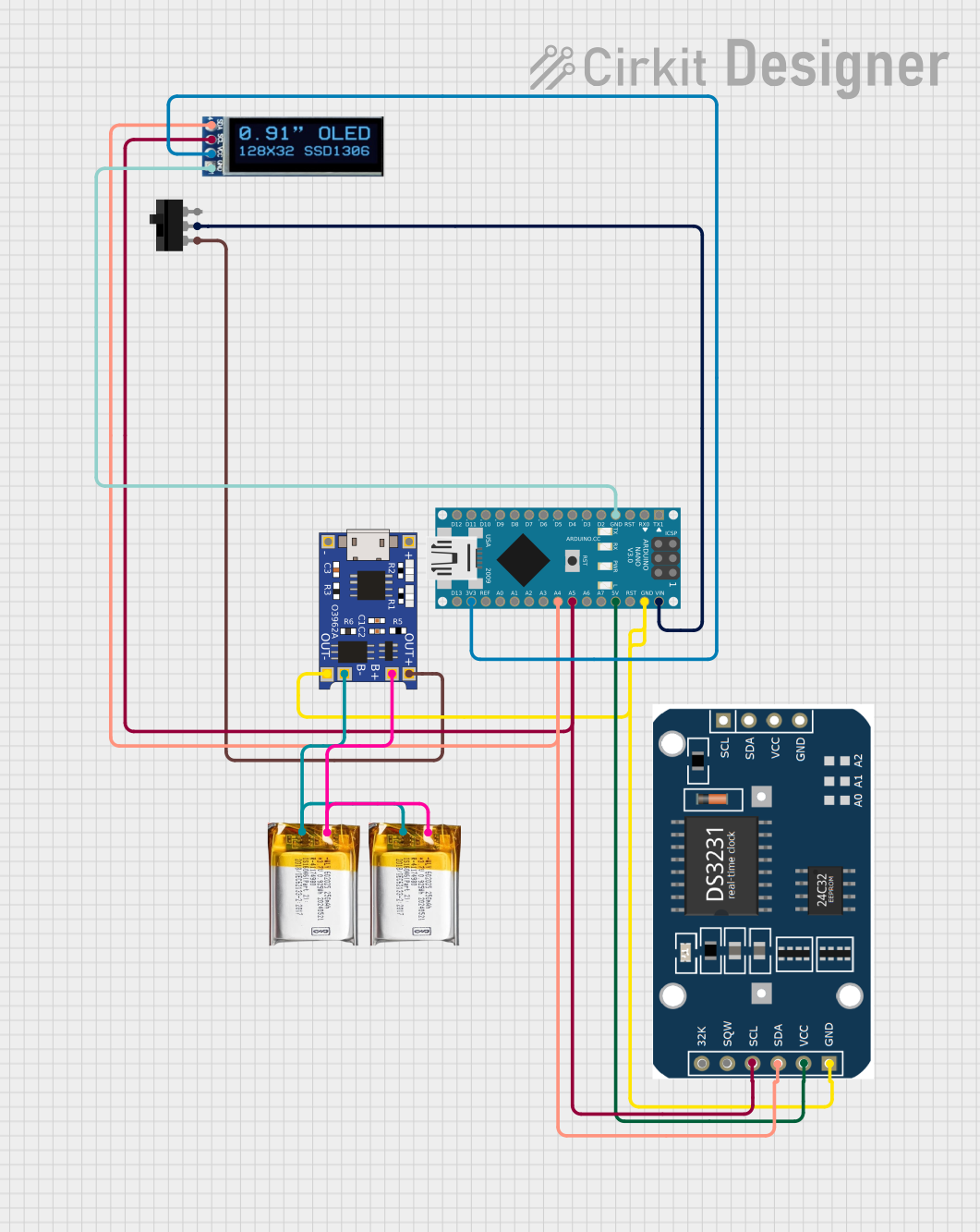
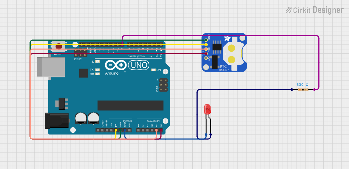

Explore Projects Built with RDM 6300
Technical Specifications
Key Technical Details
- Operating Frequency: 125 kHz
- Interface: UART (TTL level)
- Baud Rate: 9600 bps (default)
- Voltage Requirements: 4.5V to 5.5V DC
- Current Consumption: 50mA (max)
- Reading Distance: Up to 10 cm (depending on the tag type)
- Antenna: Built-in, external antenna not required
- Dimensions: Typically around 38.5 x 19 x 9 mm
Pin Configuration and Descriptions
| Pin Number | Pin Name | Description |
|---|---|---|
| 1 | VCC | Power supply (4.5V to 5.5V DC) |
| 2 | TX | Transmit data (TTL level) |
| 3 | RX | Receive data (TTL level, not commonly used) |
| 4 | GND | Ground |
Usage Instructions
Integration with a Circuit
To use the RDM 6300 with a microcontroller like the Arduino UNO, follow these steps:
- Connect the VCC pin of the RDM 6300 to the 5V output on the Arduino.
- Connect the GND pin to one of the GND pins on the Arduino.
- Connect the TX pin of the RDM 6300 to a digital pin on the Arduino configured as a serial RX pin.
- The RX pin of the RDM 6300 is typically not used, as the module only sends data to the microcontroller.
Important Considerations and Best Practices
- Ensure that the power supply is stable and within the specified voltage range to prevent damage to the module.
- Place the RFID tags close to the module for optimal reading.
- Avoid placing the module near metal surfaces or electronic devices that may cause interference.
- Use proper ESD precautions when handling the module to prevent static damage.
Example Code for Arduino UNO
#include <SoftwareSerial.h>

SoftwareSerial RFID(10, 11); // RX and TX pins
char tagString[13];          // Array to store RFID tag data
int bytesread = 0;           // Counter for tag data

void setup() {
  RFID.begin(9600);          // Start serial to RFID reader
  Serial.begin(9600);        // Start serial to PC
}

void loop() {
  if (RFID.available() > 0) {
    // Read tag data from RDM 6300
    if((val = RFID.read()) == 2) { // Check for header
      bytesread = 0;
      while (bytesread < 12) { // Read 10 digit code + 2 digit checksum
        if( RFID.available() > 0) {
          val = RFID.read();
          if((val == 0x0D)||(val == 0x0A)||(val == 0x03)) {
            // If header or stop bytes before the 10 digit reading
            break; // Stop reading
          }
          tagString[bytesread] = val; // Add the byte to the tagString
          bytesread++;                 // Ready to read next digit
        }
      }
      if(bytesread == 12) { // If 12 digit read is complete
        Serial.print("TAG code is: "); // Output to serial monitor
        for(int i = 0; i < 12; i++) {
          Serial.print(tagString[i]);
        }
        Serial.println();
      }
      bytesread = 0;
      delay(500); // Wait for a bit before reading again
    }
  }
}
Troubleshooting and FAQs
Common Issues
- Tag not reading: Ensure the tag is within the operational range and the antenna is not obstructed.
- No data on serial: Check the wiring, especially the TX pin connection to the Arduino.
- Erratic readings: Ensure there is no interference from nearby electronic devices or metal surfaces.
Solutions and Tips for Troubleshooting
- Double-check all connections and ensure they are secure.
- Verify that the baud rate of the serial connection matches the default baud rate of the RDM 6300.
- Reset the Arduino and the RDM 6300 module if the system is unresponsive.
- Check the power supply for stability and correct voltage.
FAQs
Q: Can the RDM 6300 write to RFID tags? A: No, the RDM 6300 is designed only to read RFID tags.
Q: What is the maximum range of the RDM 6300? A: The maximum reading distance is up to 10 cm, but this can vary depending on the tag and environmental conditions.
Q: Can the RDM 6300 be used with other microcontrollers? A: Yes, as long as the microcontroller supports UART communication and operates within the voltage range of the RDM 6300.
Q: Is it necessary to use the RX pin on the RDM 6300? A: For most applications, only the TX pin is used to transmit the tag data to the microcontroller. The RX pin is not commonly used.
This documentation provides a comprehensive guide to using the RDM 6300 RFID reader module. For further assistance or technical support, please consult the community forums or contact the manufacturer directly.