How to Use MCP1700 LDO: Examples, Pinouts, and Specs

 Design with MCP1700 LDO in Cirkit Designer
Introduction
The MCP1700 is a low dropout (LDO) voltage regulator manufactured by Bridgold. It is designed to provide a stable output voltage with a low quiescent current, making it ideal for battery-powered applications. The MCP1700 is particularly useful in scenarios where power efficiency is critical, such as in portable electronics, microcontroller power supplies, and low-power sensors.
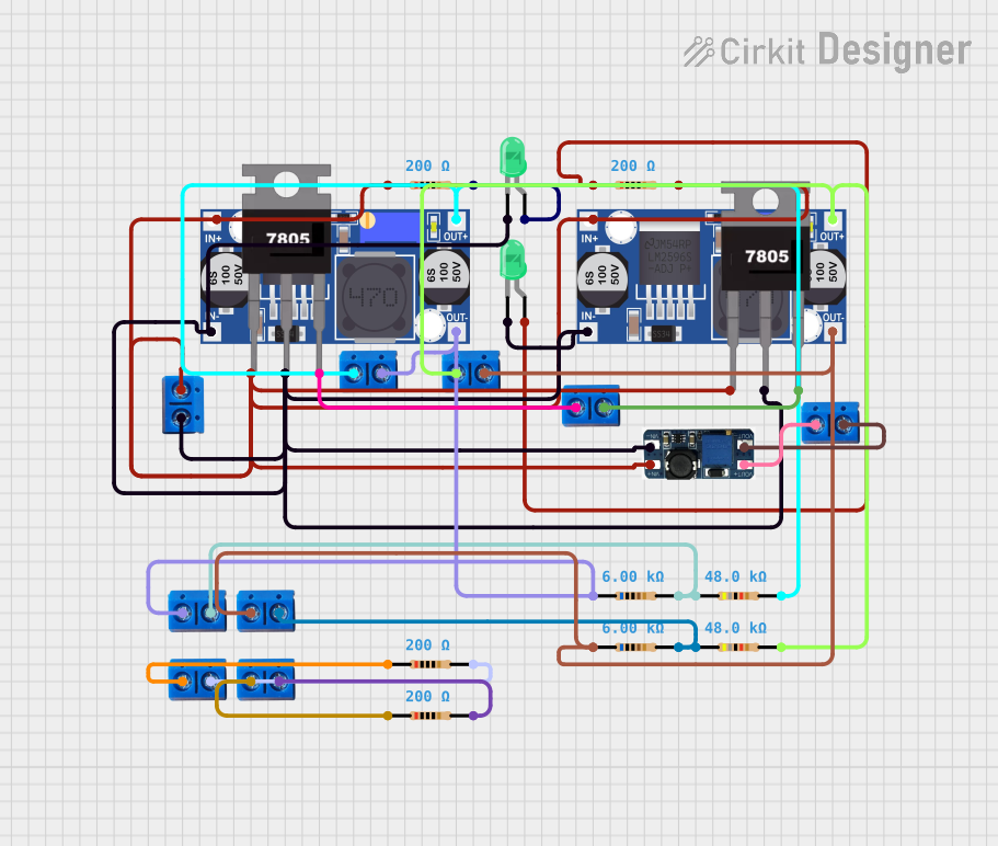
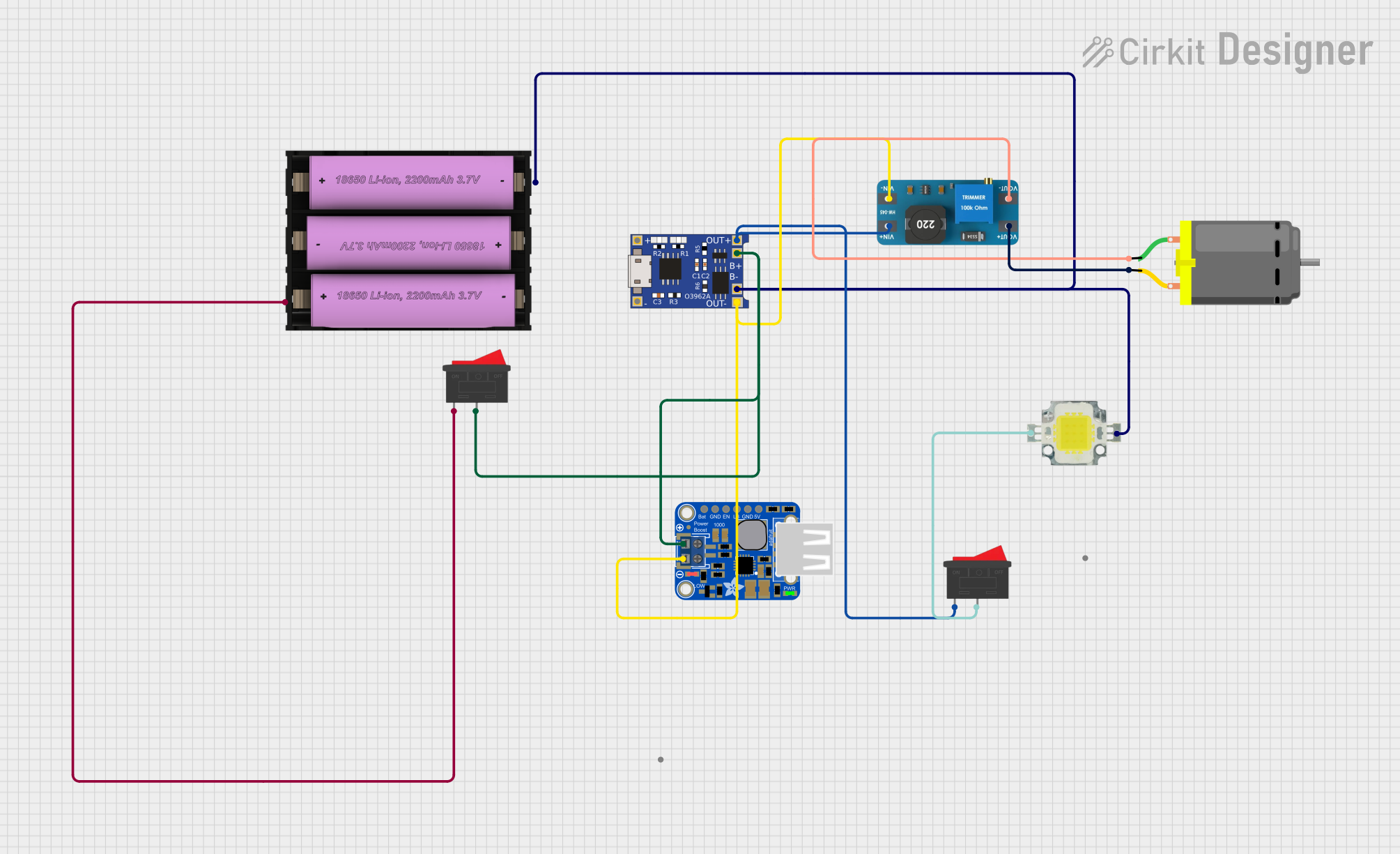
Explore Projects Built with MCP1700 LDO

 Open Project in Cirkit Designer
 Open Project in Cirkit Designer
 Open Project in Cirkit Designer
 Open Project in Cirkit Designer
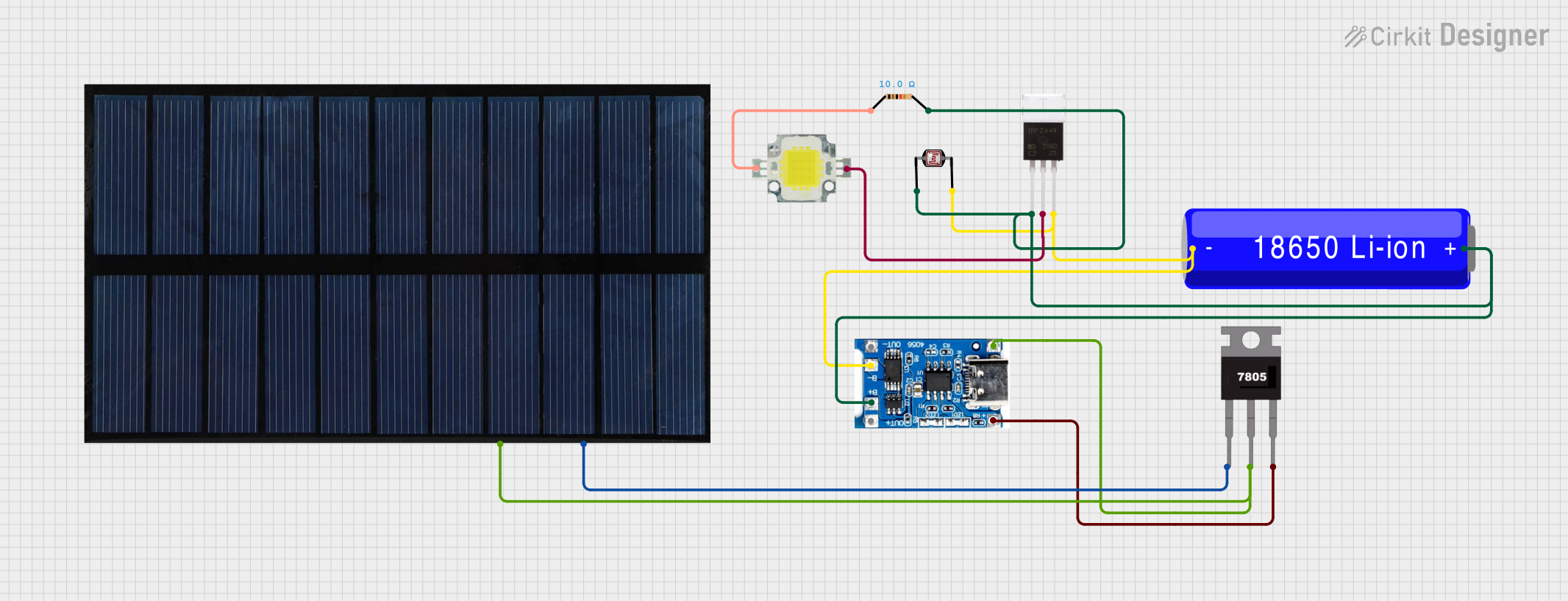
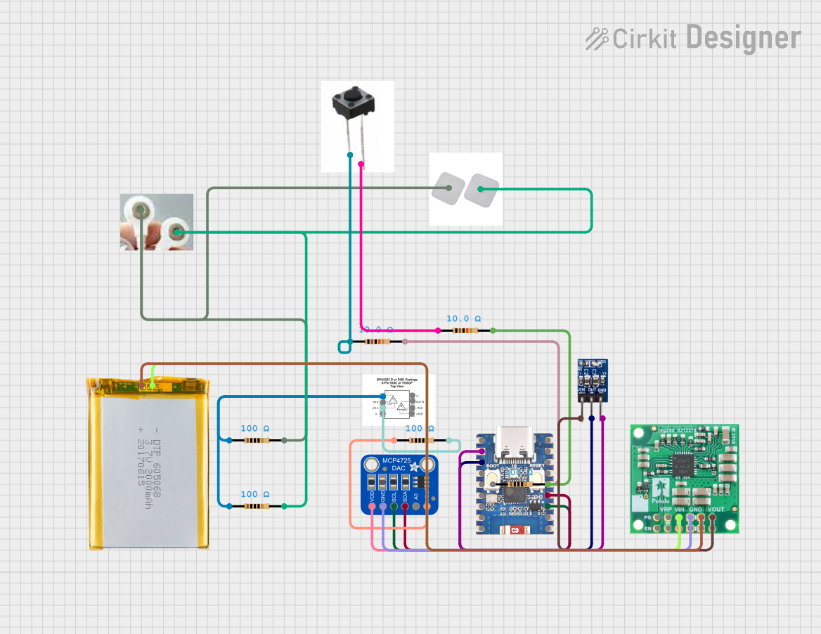
Explore Projects Built with MCP1700 LDO

 Open Project in Cirkit Designer
 Open Project in Cirkit Designer
 Open Project in Cirkit Designer
 Open Project in Cirkit Designer
Technical Specifications
Key Technical Details
| Parameter | Value |
|---|---|
| Manufacturer | Bridgold |
| Part ID | MCP1700 |
| Output Voltage Options | 1.2V, 1.5V, 1.8V, 2.5V, 3.0V, 3.3V, 5.0V |
| Input Voltage Range | 2.3V to 6.0V |
| Output Current | Up to 250mA |
| Dropout Voltage | 178mV @ 250mA (typical) |
| Quiescent Current | 1.6µA (typical) |
| Operating Temperature | -40°C to +125°C |
| Package Options | SOT-23-3, SOT-89-3 |
Pin Configuration and Descriptions
SOT-23-3 Package
| Pin Number | Pin Name | Description |
|---|---|---|
| 1 | VIN | Input Voltage |
| 2 | GND | Ground |
| 3 | VOUT | Regulated Output Voltage |
SOT-89-3 Package
| Pin Number | Pin Name | Description |
|---|---|---|
| 1 | VIN | Input Voltage |
| 2 | GND | Ground |
| 3 | VOUT | Regulated Output Voltage |
Usage Instructions
How to Use the MCP1700 in a Circuit
Connect the Input Voltage (VIN): Connect the input voltage to the VIN pin. Ensure that the input voltage is within the specified range (2.3V to 6.0V).
Connect the Ground (GND): Connect the GND pin to the ground of your circuit.
Connect the Output Voltage (VOUT): Connect the VOUT pin to the load that requires the regulated voltage.
Add Capacitors: It is recommended to add a capacitor (typically 1µF) between the VIN pin and GND, and another capacitor (typically 1µF) between the VOUT pin and GND to ensure stability and reduce noise.
Important Considerations and Best Practices
- Input Voltage: Ensure that the input voltage is always higher than the desired output voltage by at least the dropout voltage.
- Thermal Management: If the MCP1700 is used in high current applications, ensure proper thermal management to avoid overheating.
- Capacitor Selection: Use low ESR capacitors for better performance and stability.
Example Circuit
Below is an example of how to connect the MCP1700 to an Arduino UNO to provide a stable 3.3V output.
// Example code to read an analog sensor using MCP1700 and Arduino UNO

const int sensorPin = A0; // Analog input pin for the sensor
int sensorValue = 0;      // Variable to store the sensor value

void setup() {
  Serial.begin(9600); // Initialize serial communication at 9600 baud
}

void loop() {
  sensorValue = analogRead(sensorPin); // Read the analog sensor value
  Serial.println(sensorValue);         // Print the sensor value to the serial monitor
  delay(1000);                         // Wait for 1 second before the next reading
}
Troubleshooting and FAQs
Common Issues
No Output Voltage:
- Solution: Check the input voltage to ensure it is within the specified range. Verify all connections and ensure capacitors are correctly placed.
Output Voltage is Unstable:
- Solution: Ensure that low ESR capacitors are used. Check for any loose connections or poor solder joints.
Overheating:
- Solution: Ensure proper thermal management. Reduce the load current if possible or use a heatsink.
FAQs
Q1: Can I use the MCP1700 with a 9V battery?
- A1: No, the maximum input voltage for the MCP1700 is 6.0V. Using a 9V battery may damage the regulator.
Q2: What is the minimum input voltage required for a 3.3V output?
- A2: The minimum input voltage should be at least 3.3V + dropout voltage (approximately 3.5V).
Q3: Can I use the MCP1700 without input and output capacitors?
- A3: It is not recommended. Input and output capacitors are essential for stability and noise reduction.
By following this documentation, users can effectively integrate the MCP1700 LDO voltage regulator into their projects, ensuring reliable and efficient power management.