
How to Use Micro USB to USB cable: Examples, Pinouts, and Specs
 Design with Micro USB to USB cable in Cirkit Designer
Introduction
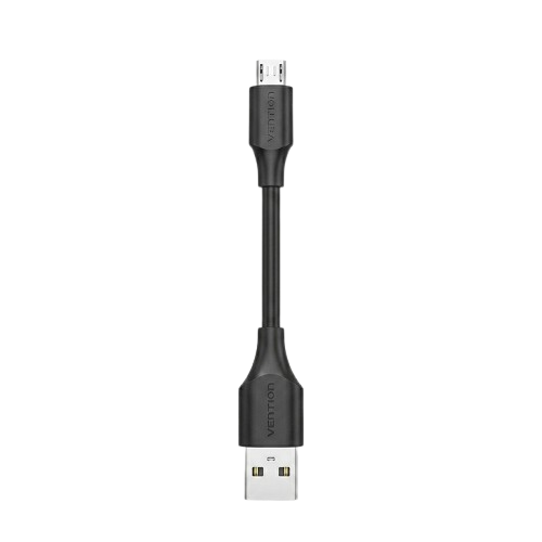
The Micro USB to USB cable is a versatile and widely used electronic component designed to connect devices with a Micro USB port to standard USB ports. It facilitates data transfer, device synchronization, and charging. This cable is commonly used with smartphones, tablets, power banks, cameras, and various other electronic devices.
Explore Projects Built with Micro USB to USB cable
 Open Project in Cirkit Designer
 Open Project in Cirkit Designer
 Open Project in Cirkit Designer
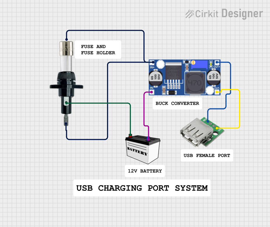 Open Project in Cirkit Designer
Explore Projects Built with Micro USB to USB cable
Open Project in Cirkit DesignerOpen Project in Cirkit DesignerOpen Project in Cirkit DesignerOpen Project in Cirkit DesignerCommon Applications and Use Cases
- Data Transfer: Transferring files between devices such as smartphones, tablets, and computers.
- Device Charging: Charging devices like smartphones, power banks, and Bluetooth accessories.
- Firmware Updates: Updating firmware on devices with Micro USB ports.
- Peripheral Connectivity: Connecting Micro USB devices to USB-enabled peripherals like printers or external storage.
Technical Specifications
The Micro USB to USB cable is available in various lengths and configurations. Below are the general technical specifications:
Key Technical Details
| Parameter | Specification |
|---|---|
| Connector Type | Micro USB (Type B) to USB (Type A) |
| Cable Length | Typically 0.5m to 3m (varies by manufacturer) |
| Data Transfer Speed | Up to 480 Mbps (USB 2.0 standard) |
| Charging Current | Up to 2.4A (depending on cable quality and device) |
| Voltage Rating | 5V (standard USB voltage) |
| Compatibility | USB 1.1, USB 2.0, USB 3.0 (data transfer limited to USB 2.0 speeds) |
Pin Configuration and Descriptions
The Micro USB to USB cable consists of four primary pins for data transfer and power delivery. The pinout is as follows:
Micro USB (Type B) Pinout
| Pin Number | Name | Description |
|---|---|---|
| 1 | VBUS | +5V power supply |
| 2 | D- | Data transfer (negative) |
| 3 | D+ | Data transfer (positive) |
| 4 | ID | Identification pin (used in OTG configurations) |
| 5 | GND | Ground |
USB (Type A) Pinout
| Pin Number | Name | Description |
|---|---|---|
| 1 | VBUS | +5V power supply |
| 2 | D- | Data transfer (negative) |
| 3 | D+ | Data transfer (positive) |
| 4 | GND | Ground |
Usage Instructions
How to Use the Component in a Circuit
- Connecting Devices:
- Plug the Micro USB connector into the device with a Micro USB port (e.g., smartphone, power bank).
- Connect the USB Type A connector to a USB port on a computer, charger, or power bank.
- Data Transfer:
- Ensure the device is set to the appropriate mode (e.g., "File Transfer" or "MTP" for Android devices).
- Use a compatible operating system (e.g., Windows, macOS, or Linux) to access the connected device.
- Charging:
- Use a power adapter or USB port that supports the required current for your device.
- Avoid using low-quality cables for high-current charging to prevent overheating.
Important Considerations and Best Practices
- Cable Quality: Use high-quality cables to ensure reliable data transfer and safe charging.
- Length Limitations: Longer cables may result in voltage drops, reducing charging efficiency.
- Compatibility: Verify that the cable supports the required current and data transfer speed for your device.
- Avoid Overbending: Do not excessively bend or twist the cable to prevent internal wire damage.
Example: Connecting to an Arduino UNO
The Micro USB to USB cable is not directly compatible with the Arduino UNO, as the UNO uses a USB Type B connector. However, if you are using a Micro USB-based Arduino board (e.g., Arduino Micro or Arduino Nano), you can use this cable for programming and power.
Here is an example of Arduino code to test communication with a Micro USB-based Arduino board:
// Simple Arduino sketch to test serial communication
void setup() {
  Serial.begin(9600); // Initialize serial communication at 9600 baud
  Serial.println("Micro USB to USB cable test started.");
}

void loop() {
  Serial.println("Hello, world!"); // Send a message over the USB connection
  delay(1000); // Wait for 1 second
}
Troubleshooting and FAQs
Common Issues Users Might Face
- Device Not Recognized:
- Cause: Faulty cable, incorrect drivers, or incompatible operating system.
- Solution: Test with a different cable, update drivers, or try another computer.
- Slow Charging:
- Cause: Low-quality cable or insufficient power supply.
- Solution: Use a high-quality cable and a power adapter with sufficient current output.
- Intermittent Connection:
- Cause: Loose connectors or damaged cable.
- Solution: Ensure connectors are securely plugged in and replace damaged cables.
- Data Transfer Fails:
- Cause: Incorrect device mode or unsupported file system.
- Solution: Set the device to "File Transfer" mode and ensure the file system is supported.
Solutions and Tips for Troubleshooting
- Inspect the Cable: Check for visible damage, such as frayed wires or bent connectors.
- Test with Another Device: Verify if the issue is with the cable or the connected device.
- Use Certified Accessories: Ensure the cable is certified for data transfer and charging.
- Update Drivers: Install the latest drivers for your device to ensure compatibility.
By following this documentation, users can effectively utilize the Micro USB to USB cable for a variety of applications while avoiding common pitfalls.