How to Use Directional Switch: Examples, Pinouts, and Specs
Introduction
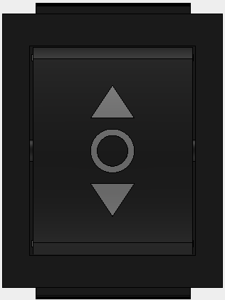
A directional switch is a device used to control the flow of electrical current in a specific direction, allowing for the selection of different circuit paths. It is commonly used in applications where the control of current flow is essential, such as in motor control, robotics, and multi-path circuit designs. Directional switches are versatile components that can be found in both manual and automated systems.
Explore Projects Built with Directional Switch
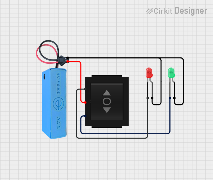
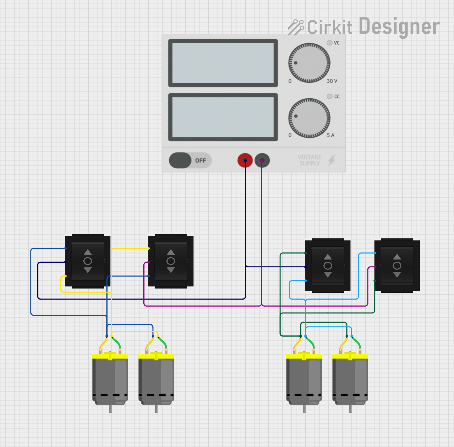
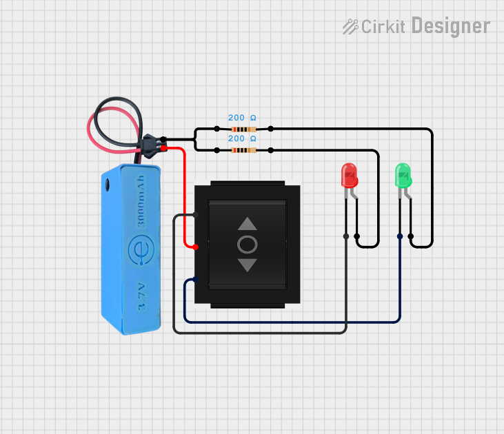
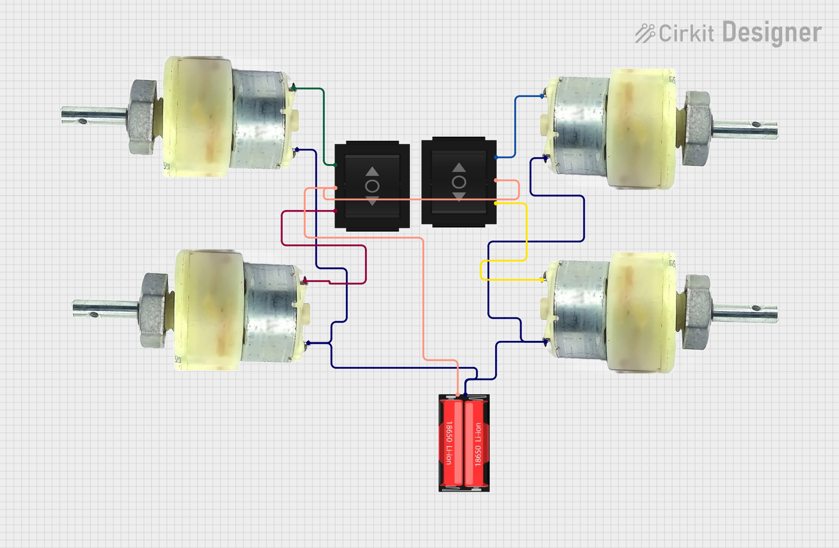
Explore Projects Built with Directional Switch
Common Applications and Use Cases
- Motor Control: Reversing the direction of DC motors in robotics or machinery.
- Circuit Selection: Switching between multiple circuit paths in testing or operational setups.
- Signal Routing: Directing signals to specific outputs in communication systems.
- Power Distribution: Controlling the flow of power to different devices or subsystems.
Technical Specifications
Below are the general technical specifications for a typical directional switch. Note that specific models may vary, so always refer to the manufacturer's datasheet for precise details.
Key Technical Details
- Operating Voltage: 3V to 24V DC (varies by model)
- Maximum Current Rating: 2A to 10A (depending on the switch type)
- Contact Resistance: ≤ 50 mΩ
- Insulation Resistance: ≥ 100 MΩ at 500V DC
- Switch Type: SPDT (Single Pole Double Throw) or DPDT (Double Pole Double Throw)
- Mechanical Life: 10,000 to 100,000 cycles
- Operating Temperature: -20°C to 70°C
Pin Configuration and Descriptions
Directional switches typically have multiple terminals, depending on the type (e.g., SPDT or DPDT). Below is an example of a DPDT switch pin configuration:
| Pin Number | Label | Description |
|---|---|---|
| 1 | Common 1 (C1) | Common terminal for the first pole. |
| 2 | Normally Open 1 (NO1) | Connected to C1 when the switch is activated. |
| 3 | Normally Closed 1 (NC1) | Connected to C1 when the switch is not activated. |
| 4 | Common 2 (C2) | Common terminal for the second pole. |
| 5 | Normally Open 2 (NO2) | Connected to C2 when the switch is activated. |
| 6 | Normally Closed 2 (NC2) | Connected to C2 when the switch is not activated. |
Usage Instructions
How to Use the Component in a Circuit
- Identify the Terminals: Refer to the pin configuration table to identify the common, normally open, and normally closed terminals.
- Connect the Circuit:
- Connect the power source or input signal to the common terminal(s).
- Connect the output devices or circuit paths to the normally open and/or normally closed terminals.
- Control the Switch:
- For manual switches, toggle the lever or button to change the connection.
- For automated switches, use a control signal (e.g., from a microcontroller) to activate the switch.
Important Considerations and Best Practices
- Current and Voltage Ratings: Ensure the switch can handle the current and voltage of your circuit to avoid damage.
- Debouncing: For applications involving microcontrollers, implement software or hardware debouncing to handle switch bounce.
- Wiring: Use appropriate wire gauges to handle the current without overheating.
- Mounting: Secure the switch properly to prevent mechanical stress or accidental disconnection.
Example: Using a Directional Switch with Arduino UNO
Below is an example of using a DPDT directional switch to control the direction of a DC motor with an Arduino UNO:
// Example: Controlling a DC motor direction with a DPDT switch and Arduino UNO

const int switchPin1 = 2; // Pin connected to the first pole of the switch
const int switchPin2 = 3; // Pin connected to the second pole of the switch
const int motorPin1 = 9;  // Pin connected to motor terminal 1
const int motorPin2 = 10; // Pin connected to motor terminal 2

void setup() {
  pinMode(switchPin1, INPUT_PULLUP); // Configure switch pin 1 as input with pull-up
  pinMode(switchPin2, INPUT_PULLUP); // Configure switch pin 2 as input with pull-up
  pinMode(motorPin1, OUTPUT);        // Configure motor pin 1 as output
  pinMode(motorPin2, OUTPUT);        // Configure motor pin 2 as output
}

void loop() {
  // Read the state of the switch
  bool switchState1 = digitalRead(switchPin1);
  bool switchState2 = digitalRead(switchPin2);

  // Control motor direction based on switch state
  if (switchState1 == LOW) {
    digitalWrite(motorPin1, HIGH); // Motor rotates in one direction
    digitalWrite(motorPin2, LOW);
  } else if (switchState2 == LOW) {
    digitalWrite(motorPin1, LOW);  // Motor rotates in the opposite direction
    digitalWrite(motorPin2, HIGH);
  } else {
    digitalWrite(motorPin1, LOW);  // Motor is off
    digitalWrite(motorPin2, LOW);
  }
}
Troubleshooting and FAQs
Common Issues Users Might Face
Switch Not Working:
- Cause: Incorrect wiring or loose connections.
- Solution: Double-check the wiring and ensure all connections are secure.
Overheating:
- Cause: Exceeding the current or voltage rating of the switch.
- Solution: Use a switch with appropriate ratings for your circuit.
Switch Bounce:
- Cause: Mechanical contacts in the switch causing rapid on/off signals.
- Solution: Implement debouncing in software or use a capacitor for hardware debouncing.
Motor Not Reversing:
- Cause: Incorrect connection of the DPDT switch terminals.
- Solution: Verify the terminal connections and ensure proper wiring.
Solutions and Tips for Troubleshooting
- Use a multimeter to test the continuity of the switch terminals.
- Check the datasheet of the specific switch model for detailed specifications.
- If using with a microcontroller, ensure the input pins are configured correctly and not left floating.
By following this documentation, you can effectively integrate a directional switch into your electronic projects and troubleshoot common issues with ease.