
How to Use DS1809: Examples, Pinouts, and Specs
 Design with DS1809 in Cirkit Designer
Introduction
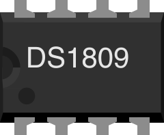
The DS1809, manufactured by Maxim Integrated, is a programmable clock generator designed to provide a wide range of clock frequencies for various applications. This component is particularly useful in microcontroller systems where precise timing signals are required. The DS1809 can be configured using external resistors, making it a versatile and cost-effective solution for generating clock signals.
Explore Projects Built with DS1809
 Open Project in Cirkit Designer
 Open Project in Cirkit Designer
 Open Project in Cirkit Designer
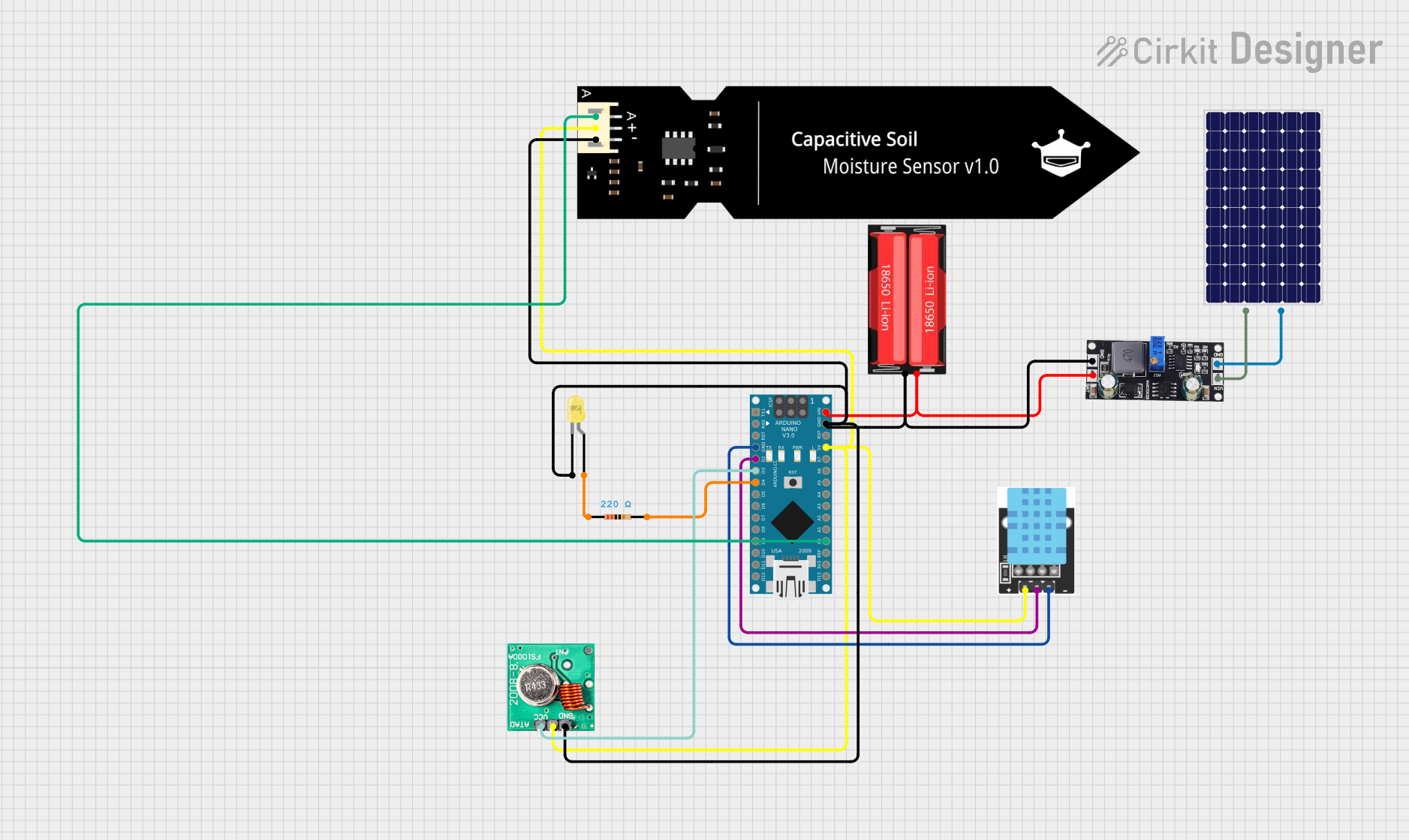 Open Project in Cirkit Designer
Explore Projects Built with DS1809
Open Project in Cirkit DesignerOpen Project in Cirkit DesignerOpen Project in Cirkit DesignerOpen Project in Cirkit DesignerCommon Applications
- Microcontroller clock generation
- Timing signal generation for digital circuits
- Frequency tuning in communication systems
- Clock synchronization in embedded systems
Technical Specifications
Key Technical Details
- Manufacturer Part ID: DS1809
- Operating Voltage: 2.7V to 5.5V
- Frequency Range: Configurable from 1 kHz to 10 MHz
- Output Signal Type: Square wave
- Configuration: External resistor-based frequency selection
- Operating Temperature Range: -40°C to +85°C
- Package Types: Available in 8-pin DIP and SOIC packages
Pin Configuration and Descriptions
The DS1809 is an 8-pin device. Below is the pinout and description:
| Pin Number | Pin Name | Description |
|---|---|---|
| 1 | VCC | Power supply input (2.7V to 5.5V). |
| 2 | GND | Ground connection. |
| 3 | OUT | Clock output pin. Outputs the generated square wave signal. |
| 4 | REXT | External resistor pin. Used to set the desired clock frequency. |
| 5 | NC | No connection. Leave this pin unconnected. |
| 6 | MODE | Mode selection pin. Determines the frequency range (low or high). |
| 7 | ENABLE | Enable pin. Active high; enables the clock output when set to HIGH. |
| 8 | RESET | Reset pin. Resets the internal configuration when pulled LOW. |
Usage Instructions
How to Use the DS1809 in a Circuit
- Power Supply: Connect the VCC pin to a stable power source (2.7V to 5.5V) and the GND pin to ground.
- Frequency Configuration:
- Connect an external resistor to the REXT pin. The value of the resistor determines the output frequency.
- Refer to the datasheet for the resistor-to-frequency mapping table.
- Mode Selection:
- Use the MODE pin to select the frequency range:
- LOW mode: For lower frequency ranges (e.g., 1 kHz to 100 kHz).
- HIGH mode: For higher frequency ranges (e.g., 100 kHz to 10 MHz).
- Tie the MODE pin to GND for LOW mode or VCC for HIGH mode.
- Use the MODE pin to select the frequency range:
- Enable Output:
- Set the ENABLE pin HIGH to activate the clock output on the OUT pin.
- Pull the ENABLE pin LOW to disable the clock output.
- Reset:
- To reset the DS1809, pull the RESET pin LOW momentarily. This will reset the internal configuration.
Important Considerations and Best Practices
- Use a decoupling capacitor (e.g., 0.1 µF) between VCC and GND to ensure stable operation.
- Avoid using excessively long traces for the REXT pin to minimize noise and interference.
- Ensure the external resistor value is within the recommended range specified in the datasheet.
- If unused, leave the NC pin unconnected.
Example: Using DS1809 with Arduino UNO
The DS1809 can be used with an Arduino UNO to generate a clock signal. Below is an example circuit and code:
Circuit Connections
- Connect the DS1809 VCC pin to the Arduino 5V pin.
- Connect the GND pin to the Arduino GND.
- Connect the OUT pin to a digital input pin on the Arduino (e.g., pin 2).
- Use a 10 kΩ resistor on the REXT pin to set the frequency.
- Tie the MODE pin to GND for LOW mode.
- Connect the ENABLE pin to Arduino pin 3 for control.
Arduino Code
// DS1809 Clock Generator Example with Arduino UNO
// This code enables and disables the DS1809 clock output using pin 3.

#define ENABLE_PIN 3  // Arduino pin connected to DS1809 ENABLE pin
#define CLOCK_INPUT 2 // Arduino pin connected to DS1809 OUT pin

void setup() {
  pinMode(ENABLE_PIN, OUTPUT); // Set ENABLE pin as output
  pinMode(CLOCK_INPUT, INPUT); // Set CLOCK_INPUT pin as input

  // Enable the DS1809 clock output
  digitalWrite(ENABLE_PIN, HIGH);
}

void loop() {
  // Read the clock signal from the DS1809 OUT pin
  int clockSignal = digitalRead(CLOCK_INPUT);

  // Perform some action based on the clock signal
  if (clockSignal == HIGH) {
    // Clock signal is HIGH
    // Add your application-specific code here
  } else {
    // Clock signal is LOW
    // Add your application-specific code here
  }

  delay(10); // Small delay for stability
}
Troubleshooting and FAQs
Common Issues and Solutions
No Output Signal on OUT Pin:
- Ensure the ENABLE pin is set HIGH.
- Verify the external resistor value on the REXT pin is within the recommended range.
- Check the power supply voltage (VCC) and ensure it is within the operating range.
Incorrect Frequency Output:
- Double-check the resistor value connected to the REXT pin.
- Verify the MODE pin configuration (LOW or HIGH mode) matches the desired frequency range.
Unstable Clock Signal:
- Add a decoupling capacitor (e.g., 0.1 µF) between VCC and GND.
- Minimize noise on the REXT pin by using short traces and avoiding interference.
Device Not Responding to RESET:
- Ensure the RESET pin is momentarily pulled LOW and then released.
- Verify the RESET pin connection and ensure it is not floating.
FAQs
Q1: Can I use a potentiometer instead of a fixed resistor on the REXT pin?
A1: Yes, a potentiometer can be used to dynamically adjust the frequency. Ensure the potentiometer value stays within the recommended range.
Q2: What happens if the ENABLE pin is left floating?
A2: The ENABLE pin should not be left floating. Tie it to GND to disable the output or to VCC to enable the output.
Q3: Can the DS1809 operate at voltages below 2.7V?
A3: No, the DS1809 requires a minimum operating voltage of 2.7V. Operating below this voltage may result in unpredictable behavior.
Q4: Is the DS1809 suitable for high-precision timing applications?
A4: The DS1809 provides good timing accuracy for general applications. For high-precision requirements, consider using a dedicated crystal oscillator.