How to Use SPD: Examples, Pinouts, and Specs
Introduction
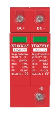
A Surge Protective Device (SPD) is an essential electronic component designed to protect electrical equipment from transient voltage spikes. These voltage surges can occur due to lightning strikes, power grid switching, or other electrical disturbances. The SPD works by diverting excess voltage to the ground, ensuring that connected devices remain safe from damage.
Explore Projects Built with SPD


Explore Projects Built with SPD
Common Applications and Use Cases
- Protection of sensitive electronic equipment such as computers, servers, and medical devices.
- Industrial applications to safeguard machinery and control systems.
- Residential use to protect home appliances and entertainment systems.
- Renewable energy systems, such as solar inverters, to prevent damage from lightning-induced surges.
- Telecommunications and data centers to ensure uninterrupted operation.
Technical Specifications
Below are the key technical details of a typical SPD:
| Parameter | Value |
|---|---|
| Nominal Voltage (Un) | 120V, 230V, 400V (varies by model) |
| Maximum Continuous Voltage (Uc) | 150V, 275V, 440V (varies by model) |
| Surge Current Capacity (Imax) | 10kA to 100kA (depending on type) |
| Voltage Protection Level (Up) | ≤ 1.5kV (varies by model) |
| Response Time | < 25 nanoseconds |
| Operating Temperature | -40°C to +85°C |
| Mounting Type | DIN rail, panel-mounted, or inline |
| Standards Compliance | IEC 61643-11, UL 1449 |
Pin Configuration and Descriptions
SPDs typically have a simple terminal configuration. Below is an example for a single-phase SPD:
| Pin | Label | Description |
|---|---|---|
| 1 | L | Line (Live) connection for incoming voltage |
| 2 | N | Neutral connection for incoming voltage |
| 3 | PE | Protective Earth (Ground) connection |
For three-phase SPDs, additional terminals (L1, L2, L3) are included for each phase.
Usage Instructions
How to Use the Component in a Circuit
- Determine the Voltage Rating: Ensure the SPD's nominal voltage (Un) matches the system voltage.
- Select the Mounting Type: Choose between DIN rail, panel-mounted, or inline SPDs based on your application.
- Connect the Terminals:
- Connect the Line (L) terminal to the live wire of the circuit.
- Connect the Neutral (N) terminal to the neutral wire.
- Connect the Protective Earth (PE) terminal to the ground.
- Verify Grounding: Ensure the grounding system is properly installed and has low impedance for effective surge diversion.
- Test the Installation: Use a surge tester or multimeter to verify proper installation and functionality.
Important Considerations and Best Practices
- Always select an SPD with a surge current capacity (Imax) suitable for your application.
- Install the SPD as close as possible to the equipment being protected to minimize lead inductance.
- Regularly inspect and maintain the SPD to ensure it remains functional, especially after a surge event.
- For three-phase systems, ensure all phases are protected by using a three-phase SPD or multiple single-phase SPDs.
- Follow local electrical codes and standards during installation.
Example: Connecting an SPD to an Arduino UNO
While SPDs are not directly connected to microcontrollers like the Arduino UNO, they can be used to protect the power supply feeding the Arduino. Below is an example of how to integrate an SPD into a circuit powering an Arduino UNO:
// Example: Protecting an Arduino UNO with an SPD
// Circuit setup:
// - SPD is installed between the power supply and the Arduino UNO.
// - Ensure the SPD's voltage rating matches the power supply voltage.

void setup() {
  // Initialize the Arduino
  Serial.begin(9600);
  Serial.println("Arduino is protected by an SPD.");
}

void loop() {
  // Main loop
  Serial.println("System running safely...");
  delay(1000); // Delay for 1 second
}
Troubleshooting and FAQs
Common Issues Users Might Face
SPD Fails to Protect Equipment:
- Cause: Incorrect voltage rating or improper installation.
- Solution: Verify the SPD's voltage rating and ensure proper wiring.
Frequent SPD Failures:
- Cause: Repeated high-energy surges or poor-quality SPD.
- Solution: Use an SPD with a higher surge current capacity (Imax) and ensure proper grounding.
SPD Overheating:
- Cause: Continuous overvoltage or poor ventilation.
- Solution: Check the system voltage and ensure the SPD is installed in a well-ventilated area.
No Indication of SPD Operation:
- Cause: Lack of a status indicator or LED on the SPD.
- Solution: Use an SPD with a built-in status indicator or test the SPD periodically.
Solutions and Tips for Troubleshooting
- Use a multimeter to check the continuity of the SPD's internal components.
- Inspect the grounding system to ensure it is functioning correctly.
- Replace the SPD if it shows signs of physical damage or if its status indicator signals failure.
- Consult the manufacturer's datasheet for specific troubleshooting steps and maintenance guidelines.