How to Use DC-DC Step-Down Buck Converter Power Supply Module 24V 12V 9V to 5V 5A 25W: Examples, Pinouts, and Specs
Introduction
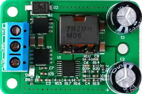
The DC-DC Step-Down Buck Converter Power Supply Module is a highly efficient voltage regulator designed to step down higher input voltages (e.g., 24V, 12V, or 9V) to a stable 5V output. It is capable of delivering up to 5A of current with a maximum power output of 25W. This module is widely used in applications requiring efficient power conversion, such as powering microcontrollers, single-board computers (e.g., Raspberry Pi, Arduino), USB devices, and other low-voltage electronics.
Explore Projects Built with DC-DC Step-Down Buck Converter Power Supply Module 24V 12V 9V to 5V 5A 25W


Explore Projects Built with DC-DC Step-Down Buck Converter Power Supply Module 24V 12V 9V to 5V 5A 25W
Common Applications
- Powering 5V devices from higher voltage sources (e.g., car batteries, solar panels).
- USB power supply for charging smartphones, tablets, or other USB-powered devices.
- Voltage regulation in embedded systems and IoT projects.
- Powering LED strips or other low-voltage lighting systems.
Technical Specifications
Key Specifications
| Parameter | Value |
|---|---|
| Input Voltage Range | 6V to 24V |
| Output Voltage | 5V (fixed) |
| Maximum Output Current | 5A |
| Maximum Power Output | 25W |
| Efficiency | Up to 96% |
| Operating Temperature | -40°C to +85°C |
| Dimensions | ~60mm x 21mm x 14mm |
Pin Configuration and Descriptions
| Pin Name | Description |
|---|---|
| VIN+ | Positive input voltage terminal (connect to the higher voltage source). |
| VIN- | Negative input voltage terminal (connect to the ground of the power source). |
| VOUT+ | Positive output voltage terminal (provides the regulated 5V output). |
| VOUT- | Negative output voltage terminal (connect to the ground of the load). |
Usage Instructions
How to Use the Module in a Circuit
Connect the Input Voltage:
- Connect the positive terminal of your power source (e.g., 12V battery) to the
VIN+pin. - Connect the ground of your power source to the
VIN-pin. - Ensure the input voltage is within the range of 6V to 24V.
- Connect the positive terminal of your power source (e.g., 12V battery) to the
Connect the Output Load:
- Connect the positive terminal of your load (e.g., a 5V device) to the
VOUT+pin. - Connect the ground of your load to the
VOUT-pin.
- Connect the positive terminal of your load (e.g., a 5V device) to the
Power On:
- Turn on the power source. The module will regulate the input voltage and provide a stable 5V output.
Verify Output:
- Use a multimeter to confirm the output voltage is 5V before connecting sensitive devices.
Important Considerations
- Heat Dissipation: At high currents (e.g., 5A), the module may generate heat. Ensure proper ventilation or use a heatsink if necessary.
- Input Voltage Range: Do not exceed the maximum input voltage of 24V to avoid damaging the module.
- Polarity: Double-check the polarity of your connections. Reversing the input or output connections can damage the module.
- Load Requirements: Ensure the connected load does not exceed the maximum power output of 25W (e.g., 5V × 5A).
Example: Using with an Arduino UNO
The module can be used to power an Arduino UNO from a 12V source. Below is an example circuit and code:
Circuit Connections
- Connect the
VIN+pin of the module to the positive terminal of a 12V power source. - Connect the
VIN-pin to the ground of the power source. - Connect the
VOUT+pin to the5Vpin of the Arduino UNO. - Connect the
VOUT-pin to theGNDpin of the Arduino UNO.
Example Code
// Example code to blink an LED using Arduino UNO powered by the buck converter
// Ensure the buck converter is providing a stable 5V output to the Arduino

const int ledPin = 13; // Pin connected to the onboard LED

void setup() {
  pinMode(ledPin, OUTPUT); // Set the LED pin as an output
}

void loop() {
  digitalWrite(ledPin, HIGH); // Turn the LED on
  delay(1000);                // Wait for 1 second
  digitalWrite(ledPin, LOW);  // Turn the LED off
  delay(1000);                // Wait for 1 second
}
Troubleshooting and FAQs
Common Issues and Solutions
No Output Voltage:
- Cause: Incorrect input connections or insufficient input voltage.
- Solution: Verify the input voltage is within the 6V to 24V range and check the polarity of the connections.
Overheating:
- Cause: High current draw or poor ventilation.
- Solution: Reduce the load current or add a heatsink to the module.
Output Voltage Not 5V:
- Cause: Faulty module or excessive load.
- Solution: Test the module with a lighter load or replace the module if necessary.
Module Not Powering the Load:
- Cause: Load exceeds the maximum power rating.
- Solution: Ensure the load does not draw more than 5A or 25W.
FAQs
Can I adjust the output voltage?
- No, this module provides a fixed 5V output and does not have an adjustable voltage feature.
Can I use this module to charge a USB device?
- Yes, the module can be used to power USB devices, but ensure the connected device does not exceed the 5A current limit.
What happens if I connect a higher input voltage (e.g., 30V)?
- Exceeding the maximum input voltage of 24V can permanently damage the module. Always stay within the specified range.
Is the module protected against short circuits?
- Some versions of this module may include short-circuit protection, but it is recommended to verify this feature in the product datasheet or test it cautiously.