How to Use kk2.1.5: Examples, Pinouts, and Specs
Introduction
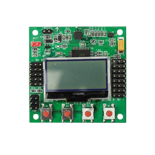
The KK2.1.5 is a flight control board designed for multirotors and other unmanned aerial vehicles (UAVs). It features an integrated 3-axis gyroscope and accelerometer, enabling precise stabilization and control during flight. The board is equipped with a user-friendly LCD interface, allowing for easy configuration and tuning of flight parameters. Its versatility and affordability make it a popular choice for hobbyists and professionals alike.
Explore Projects Built with kk2.1.5


Explore Projects Built with kk2.1.5
Common Applications and Use Cases
- Multirotor drones (quadcopters, hexacopters, octocopters)
- Fixed-wing UAVs
- RC helicopters
- Aerial photography and videography platforms
- Educational and experimental UAV projects
Technical Specifications
The KK2.1.5 flight control board is designed to provide reliable performance and flexibility for a wide range of UAV applications. Below are its key technical details:
Key Technical Details
- Processor: Atmel ATmega644PA 8-bit microcontroller
- Sensors:
- 3-axis gyroscope (6050 MPU)
- 3-axis accelerometer (6050 MPU)
- Input Voltage: 4.8V to 6.0V (via receiver or external BEC)
- Dimensions: 50.5mm x 50.5mm x 12mm
- Weight: 21 grams
- Display: 128x64 pixel LCD screen
- Firmware: Preloaded with KK2.1.5 firmware (upgradable via USBasp programmer)
- Output: 8 motor outputs (PWM)
- Input: 6-channel receiver input (PWM or PPM)
Pin Configuration and Descriptions
The KK2.1.5 board has several connectors for input and output. Below is a detailed description of its pin layout:
Motor Output Pins
| Pin Number | Label | Description |
|---|---|---|
| 1 | M1 | Motor 1 output (PWM signal) |
| 2 | M2 | Motor 2 output (PWM signal) |
| 3 | M3 | Motor 3 output (PWM signal) |
| 4 | M4 | Motor 4 output (PWM signal) |
| 5 | M5 | Motor 5 output (PWM signal) |
| 6 | M6 | Motor 6 output (PWM signal) |
| 7 | M7 | Motor 7 output (PWM signal) |
| 8 | M8 | Motor 8 output (PWM signal) |
Receiver Input Pins
| Pin Number | Label | Description |
|---|---|---|
| 1 | AIL | Aileron input (PWM/PPM signal) |
| 2 | ELE | Elevator input (PWM/PPM signal) |
| 3 | THR | Throttle input (PWM/PPM signal) |
| 4 | RUD | Rudder input (PWM/PPM signal) |
| 5 | AUX | Auxiliary input (e.g., flight mode) |
| 6 | AUX2 | Second auxiliary input (optional) |
Power and Other Connectors
| Pin Label | Description |
|---|---|
| BATT | Power input (4.8V to 6.0V) |
| ISP | In-System Programming header for firmware updates |
| BUZZER | Connector for external buzzer |
Usage Instructions
How to Use the KK2.1.5 in a Circuit
- Powering the Board: Connect a 4.8V to 6.0V power source to the BATT pins. This can be done via the receiver or an external BEC.
- Connecting Motors: Attach the ESC signal wires to the motor output pins (M1 to M8) based on your multirotor configuration (e.g., quadcopter, hexacopter).
- Connecting the Receiver: Connect the receiver channels (AIL, ELE, THR, RUD, AUX) to the corresponding input pins on the KK2.1.5.
- Calibrating the Sensors: Use the onboard LCD and buttons to navigate the menu and perform sensor calibration (e.g., accelerometer calibration).
- Configuring Flight Modes: Set up flight modes and adjust PID settings through the LCD interface for optimal performance.
- Firmware Updates: If needed, update the firmware using a USBasp programmer and the appropriate software (e.g., KK Multicopter Flash Tool).
Important Considerations and Best Practices
- ESC Calibration: Ensure all ESCs are calibrated to provide consistent throttle response.
- Propeller Orientation: Verify that propellers are installed correctly and match the motor rotation direction.
- Vibration Dampening: Use vibration-dampening mounts to reduce noise affecting the gyroscope and accelerometer.
- Failsafe Settings: Configure failsafe settings on your receiver to ensure safe operation in case of signal loss.
- Firmware Compatibility: Always use firmware compatible with the KK2.1.5 to avoid bricking the board.
Example Code for Arduino UNO Integration
While the KK2.1.5 is a standalone flight controller, it can be interfaced with an Arduino UNO for additional functionality, such as telemetry or custom control. Below is an example of reading receiver signals using the Arduino:
// Example: Reading PWM signals from the KK2.1.5 receiver output
// Connect the receiver's AIL pin to Arduino pin 2

const int receiverPin = 2; // Pin connected to the receiver's AIL output
volatile unsigned long pulseStart = 0;
volatile unsigned long pulseWidth = 0;

void setup() {
  pinMode(receiverPin, INPUT);
  Serial.begin(9600);

  // Attach interrupt to measure PWM signal
  attachInterrupt(digitalPinToInterrupt(receiverPin), measurePulse, CHANGE);
}

void loop() {
  // Print the pulse width (in microseconds) to the Serial Monitor
  Serial.print("Pulse Width: ");
  Serial.print(pulseWidth);
  Serial.println(" us");
  delay(100);
}

void measurePulse() {
  if (digitalRead(receiverPin) == HIGH) {
    // Rising edge detected, record the start time
    pulseStart = micros();
  } else {
    // Falling edge detected, calculate the pulse width
    pulseWidth = micros() - pulseStart;
  }
}
Troubleshooting and FAQs
Common Issues and Solutions
Board Not Powering On
- Cause: Insufficient or incorrect power supply.
- Solution: Ensure the input voltage is between 4.8V and 6.0V. Check all power connections.
Motors Not Spinning
- Cause: Incorrect motor connections or ESC calibration.
- Solution: Verify motor connections to the correct output pins (M1 to M8). Calibrate the ESCs.
Unstable Flight
- Cause: Incorrect PID settings or sensor calibration.
- Solution: Recalibrate the accelerometer and gyroscope. Adjust PID values for stability.
No Display on LCD
- Cause: Faulty LCD connection or damaged board.
- Solution: Check the LCD connector for loose connections. Replace the LCD if necessary.
Firmware Update Fails
- Cause: Incorrect firmware or USBasp connection.
- Solution: Ensure the firmware is compatible with the KK2.1.5. Verify the USBasp connections and drivers.
FAQs
Can the KK2.1.5 be used with GPS modules?
- No, the KK2.1.5 does not natively support GPS functionality.
What is the maximum number of motors supported?
- The KK2.1.5 supports up to 8 motors.
Can I use the KK2.1.5 for fixed-wing aircraft?
- Yes, the KK2.1.5 can be configured for fixed-wing UAVs.
Is the KK2.1.5 compatible with PPM receivers?
- Yes, the KK2.1.5 supports both PWM and PPM receiver inputs.