Cirkit Designer Logo
Cirkit Designer
Your all-in-one circuit design IDE
Home / 
Component Documentation

How to Use dec1 vtx: Examples, Pinouts, and Specs

Image of dec1 vtx
Cirkit Designer LogoDesign with dec1 vtx in Cirkit Designer

Introduction

The DEC1 VTX is a versatile video transmitter module designed for high-performance wireless video transmission. Manufactured by DEC, the VTX is widely used in applications such as FPV (First Person View) drones, wireless surveillance systems, and remote video broadcasting. Its compact design, robust signal transmission, and compatibility with various video formats make it a popular choice for both hobbyists and professionals.

Explore Projects Built with dec1 vtx

Use Cirkit Designer to design, explore, and prototype these projects online. Some projects support real-time simulation. Click "Open Project" to start designing instantly!
ESP32 and Logic Level Converter-Based Wi-Fi Controlled Interface
Image of Toshiba AC ESP32 devkit v1: A project utilizing dec1 vtx in a practical application
This circuit features an ESP32 Devkit V1 microcontroller connected to a Bi-Directional Logic Level Converter, which facilitates voltage level shifting between the ESP32 and external components. The ESP32 is powered through its VIN pin via an alligator clip cable, and the logic level converter is connected to various pins on the ESP32 to manage different voltage levels for communication.
Cirkit Designer LogoOpen Project in Cirkit Designer
Satellite-Based Timing and Navigation System with SDR and Atomic Clock Synchronization
Image of GPS 시스템 측정 구성도_Confirm: A project utilizing dec1 vtx in a practical application
This circuit appears to be a complex system involving power supply management, GPS and timing synchronization, and data communication. It includes a SI-TEX G1 Satellite Compass for GPS data, an XHTF1021 Atomic Rubidium Clock for precise timing, and Ettus USRP B200 units for software-defined radio communication. Power is supplied through various SMPS units and distributed via terminal blocks and DC jacks. Data communication is facilitated by Beelink MINI S12 N95 computers, RS232 splitters, and a 1000BASE-T Media Converter for network connectivity. RF Directional Couplers are used to interface antennas with the USRP units, and the entire system is likely contained within cases for protection and organization.
Cirkit Designer LogoOpen Project in Cirkit Designer
Configurable Battery-Powered RF Signal Transmitter with DIP Switch Settings
Image of fyp transmitter: A project utilizing dec1 vtx in a practical application
This circuit appears to be a configurable encoder system with an RF transmission capability. The encoder's address pins (A0-A7) are connected to a DIP switch for setting the address, and its data output (DO) is connected to an RF transmitter, allowing the encoded signal to be wirelessly transmitted. The circuit is powered by a 9V battery, regulated to 5V by a 7805 voltage regulator, and includes a diode for polarity protection. Tactile switches are connected to the encoder's data inputs (D1-D3), and an LED with a current-limiting resistor indicates power or activity.
Cirkit Designer LogoOpen Project in Cirkit Designer
Satellite Compass and Network-Integrated GPS Data Processing System
Image of GPS 시스템 측정 구성도_241016: A project utilizing dec1 vtx in a practical application
This circuit comprises a satellite compass, a mini PC, two GPS antennas, power supplies, a network switch, media converters, and an atomic rubidium clock. The satellite compass is powered by a triple output DC power supply and interfaces with an RS232 splitter for 1PPS signals. The mini PCs are connected to the USRP B200 devices via USB for data and power, and to media converters via Ethernet, which in turn connect to a network switch using fiber optic links. The antennas are connected to the USRP B200s through RF directional couplers, and the atomic clock provides a 1PPS input to the RS232 splitter.
Cirkit Designer LogoOpen Project in Cirkit Designer

Explore Projects Built with dec1 vtx

Use Cirkit Designer to design, explore, and prototype these projects online. Some projects support real-time simulation. Click "Open Project" to start designing instantly!
Image of Toshiba AC ESP32 devkit v1: A project utilizing dec1 vtx in a practical application
ESP32 and Logic Level Converter-Based Wi-Fi Controlled Interface
This circuit features an ESP32 Devkit V1 microcontroller connected to a Bi-Directional Logic Level Converter, which facilitates voltage level shifting between the ESP32 and external components. The ESP32 is powered through its VIN pin via an alligator clip cable, and the logic level converter is connected to various pins on the ESP32 to manage different voltage levels for communication.
Cirkit Designer LogoOpen Project in Cirkit Designer
Image of GPS 시스템 측정 구성도_Confirm: A project utilizing dec1 vtx in a practical application
Satellite-Based Timing and Navigation System with SDR and Atomic Clock Synchronization
This circuit appears to be a complex system involving power supply management, GPS and timing synchronization, and data communication. It includes a SI-TEX G1 Satellite Compass for GPS data, an XHTF1021 Atomic Rubidium Clock for precise timing, and Ettus USRP B200 units for software-defined radio communication. Power is supplied through various SMPS units and distributed via terminal blocks and DC jacks. Data communication is facilitated by Beelink MINI S12 N95 computers, RS232 splitters, and a 1000BASE-T Media Converter for network connectivity. RF Directional Couplers are used to interface antennas with the USRP units, and the entire system is likely contained within cases for protection and organization.
Cirkit Designer LogoOpen Project in Cirkit Designer
Image of fyp transmitter: A project utilizing dec1 vtx in a practical application
Configurable Battery-Powered RF Signal Transmitter with DIP Switch Settings
This circuit appears to be a configurable encoder system with an RF transmission capability. The encoder's address pins (A0-A7) are connected to a DIP switch for setting the address, and its data output (DO) is connected to an RF transmitter, allowing the encoded signal to be wirelessly transmitted. The circuit is powered by a 9V battery, regulated to 5V by a 7805 voltage regulator, and includes a diode for polarity protection. Tactile switches are connected to the encoder's data inputs (D1-D3), and an LED with a current-limiting resistor indicates power or activity.
Cirkit Designer LogoOpen Project in Cirkit Designer
Image of GPS 시스템 측정 구성도_241016: A project utilizing dec1 vtx in a practical application
Satellite Compass and Network-Integrated GPS Data Processing System
This circuit comprises a satellite compass, a mini PC, two GPS antennas, power supplies, a network switch, media converters, and an atomic rubidium clock. The satellite compass is powered by a triple output DC power supply and interfaces with an RS232 splitter for 1PPS signals. The mini PCs are connected to the USRP B200 devices via USB for data and power, and to media converters via Ethernet, which in turn connect to a network switch using fiber optic links. The antennas are connected to the USRP B200s through RF directional couplers, and the atomic clock provides a 1PPS input to the RS232 splitter.
Cirkit Designer LogoOpen Project in Cirkit Designer

Technical Specifications

The DEC1 VTX is engineered to deliver reliable performance under various operating conditions. Below are its key technical specifications:

General Specifications

  • Manufacturer: DEC
  • Part ID: VTX
  • Operating Voltage: 7V to 24V DC
  • Power Consumption: 600mW (typical)
  • Frequency Range: 5.8 GHz (selectable channels)
  • Video Input Format: NTSC/PAL
  • Output Power: 25mW, 200mW, 500mW, 800mW (adjustable)
  • Antenna Connector: SMA (standard)
  • Dimensions: 36mm x 36mm x 8mm
  • Weight: 12g (without antenna)

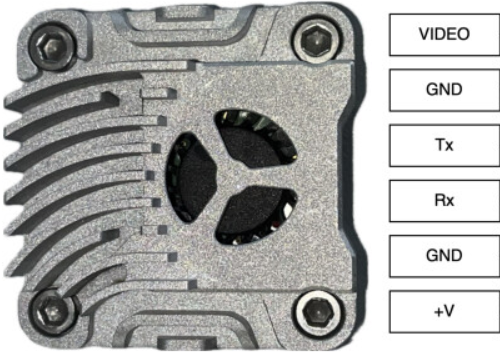
Pin Configuration and Descriptions

The DEC1 VTX features a 6-pin header for power, video input, and control. The pinout is as follows:

Pin Number Pin Name Description
1 GND Ground connection
2 VIN Power input (7V to 24V DC)
3 VIDEO_IN Analog video input (NTSC/PAL signal)
4 AUDIO_IN Analog audio input (optional)
5 CH_SEL Channel selection input (via button or UART)
6 PWR_SEL Power level selection input (via button or UART)

Usage Instructions

How to Use the DEC1 VTX in a Circuit

  1. Power Connection: Connect the VIN pin to a DC power source within the range of 7V to 24V. Ensure the GND pin is connected to the ground of the power source.
  2. Video Input: Feed an analog video signal (NTSC or PAL) into the VIDEO_IN pin. This can be sourced from a camera or other video device.
  3. Audio Input (Optional): If audio transmission is required, connect an analog audio signal to the AUDIO_IN pin.
  4. Channel and Power Selection: Use the CH_SEL and PWR_SEL pins to configure the operating frequency and output power. This can be done via a button interface or UART communication.
  5. Antenna Connection: Attach a compatible SMA antenna to the antenna connector for optimal signal transmission.

Important Considerations and Best Practices

  • Heat Management: The DEC1 VTX can generate significant heat during operation, especially at higher power levels. Ensure adequate ventilation or use a heat sink to prevent overheating.
  • Antenna Usage: Always connect an antenna before powering on the VTX to avoid damage to the RF circuitry.
  • Frequency Selection: Ensure the selected frequency does not interfere with other devices in the vicinity. Check local regulations for permissible frequency bands.
  • Power Supply: Use a stable and noise-free power source to avoid video signal distortion.

Example: Connecting to an Arduino UNO

The DEC1 VTX can be controlled via UART communication with an Arduino UNO. Below is an example code snippet for configuring the channel and power level:

#include <SoftwareSerial.h>

// Define RX and TX pins for SoftwareSerial
SoftwareSerial vtxSerial(10, 11); // RX = Pin 10, TX = Pin 11

void setup() {
  // Initialize serial communication with the VTX
  vtxSerial.begin(9600);
  Serial.begin(9600);
  
  // Set channel and power level
  setVTXChannel(3); // Set to channel 3
  setVTXPower(2);   // Set power level to 200mW
}

void loop() {
  // Main loop does nothing in this example
}

// Function to set the VTX channel
void setVTXChannel(int channel) {
  if (channel < 1 || channel > 8) {
    Serial.println("Invalid channel. Choose between 1 and 8.");
    return;
  }
  vtxSerial.write(0xA0 | (channel - 1)); // Send channel command
  Serial.print("Channel set to: ");
  Serial.println(channel);
}

// Function to set the VTX power level
void setVTXPower(int level) {
  if (level < 1 || level > 4) {
    Serial.println("Invalid power level. Choose between 1 and 4.");
    return;
  }
  vtxSerial.write(0xB0 | (level - 1)); // Send power level command
  Serial.print("Power level set to: ");
  Serial.println(level == 1 ? "25mW" : level == 2 ? "200mW" : 
                 level == 3 ? "500mW" : "800mW");
}

Troubleshooting and FAQs

Common Issues

  1. No Video Signal Output

    • Cause: Incorrect video input connection or incompatible video format.
    • Solution: Verify the VIDEO_IN connection and ensure the video source is outputting an NTSC or PAL signal.
  2. Overheating

    • Cause: Prolonged operation at high power levels without proper cooling.
    • Solution: Add a heat sink or improve ventilation around the VTX.
  3. Poor Signal Quality

    • Cause: Interference from other devices or improper antenna placement.
    • Solution: Change the operating frequency to a less congested channel and ensure the antenna is securely connected and positioned correctly.
  4. VTX Not Responding to UART Commands

    • Cause: Incorrect baud rate or wiring.
    • Solution: Verify the UART connection and ensure the baud rate is set to 9600.

FAQs

  • Q: Can the DEC1 VTX operate without an antenna?
    A: No, operating the VTX without an antenna can damage the RF circuitry.

  • Q: How do I know which channel is currently selected?
    A: The VTX typically has an LED indicator or display to show the active channel.

  • Q: Can I use the DEC1 VTX with a 5V power source?
    A: No, the minimum operating voltage is 7V. Using a lower voltage may result in malfunction or damage.

  • Q: Is the DEC1 VTX compatible with digital video signals?
    A: No, the VTX only supports analog video signals in NTSC or PAL format.