
How to Use ZVS Driver: Examples, Pinouts, and Specs
 Design with ZVS Driver in Cirkit Designer
Introduction
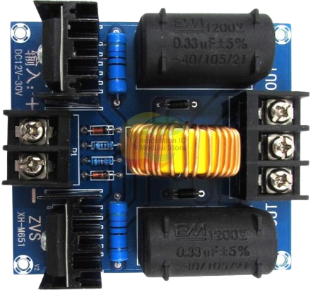
A Zero Voltage Switching (ZVS) driver is a specialized circuit designed to enable efficient switching of power transistors. By ensuring that the transistors turn on and off at zero voltage, the ZVS driver minimizes switching losses and reduces heat generation. This makes it an ideal choice for high-frequency applications where efficiency and thermal management are critical.
Explore Projects Built with ZVS Driver
 Open Project in Cirkit Designer
 Open Project in Cirkit Designer
 Open Project in Cirkit Designer
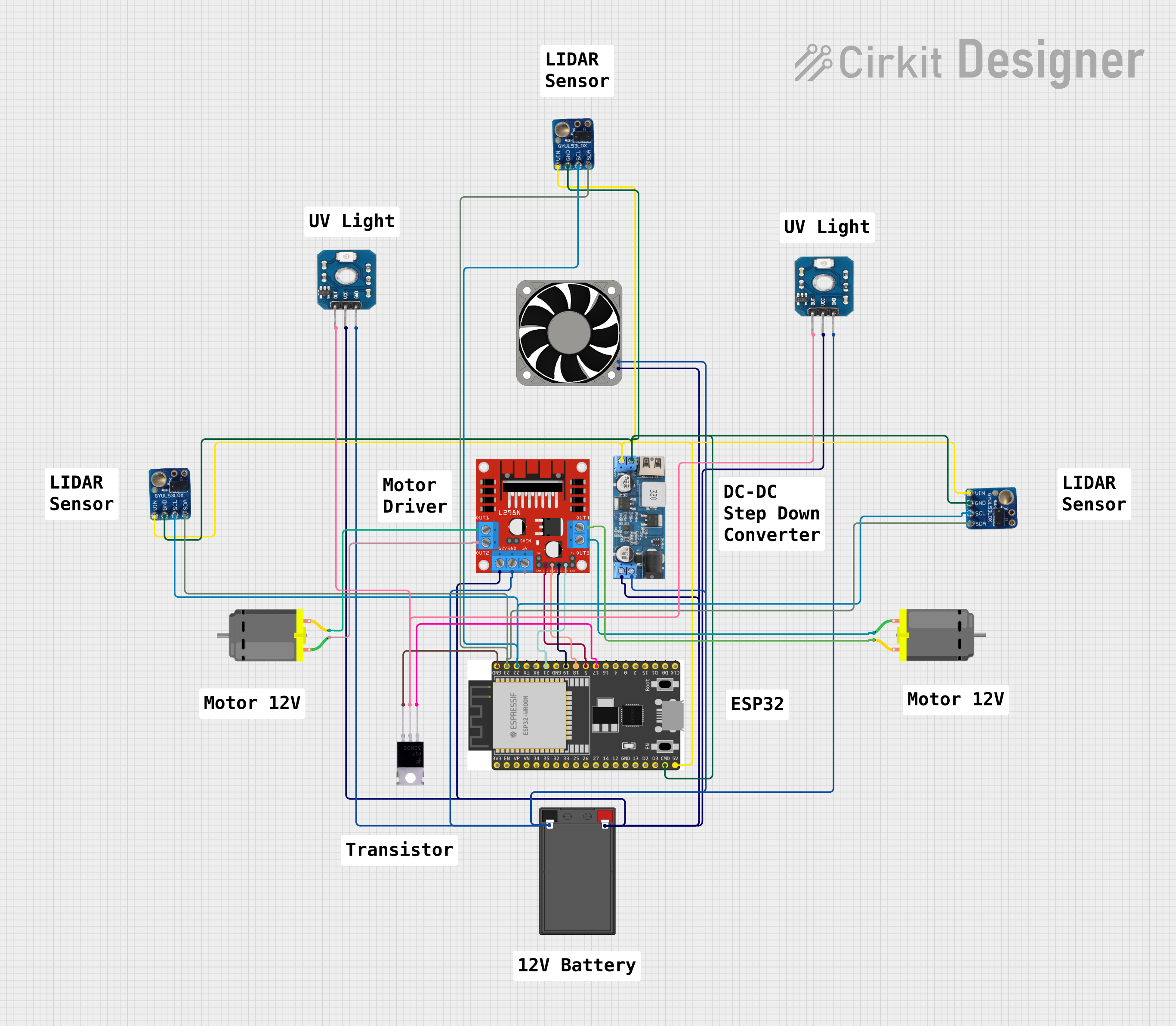 Open Project in Cirkit Designer
Explore Projects Built with ZVS Driver
Open Project in Cirkit DesignerOpen Project in Cirkit DesignerOpen Project in Cirkit DesignerOpen Project in Cirkit DesignerCommon Applications and Use Cases
- Resonant converters and inverters
- Induction heating systems
- High-frequency power supplies
- Wireless power transfer systems
- LED drivers and motor controllers
Technical Specifications
Below are the key technical details for a typical ZVS driver module:
General Specifications
- Input Voltage Range: 12V to 36V DC (varies by model)
- Output Power: Up to 100W (depending on input voltage and load)
- Switching Frequency: 20 kHz to 1 MHz (varies with load and circuit design)
- Efficiency: >90% under optimal conditions
- Operating Temperature: -20°C to 85°C
Pin Configuration and Descriptions
The ZVS driver module typically has the following pin configuration:
| Pin Name | Description |
|---|---|
| V+ | Positive DC input voltage (12V to 36V). Connect to the power supply's positive terminal. |
| V- | Negative DC input voltage (ground). Connect to the power supply's ground terminal. |
| Output+ | Positive output terminal. Connect to the load (e.g., resonant tank circuit). |
| Output- | Negative output terminal. Connect to the load's ground. |
Usage Instructions
How to Use the ZVS Driver in a Circuit
Power Supply Connection:
- Connect the V+ pin to the positive terminal of a DC power supply (12V to 36V).
- Connect the V- pin to the ground terminal of the power supply.
- Ensure the power supply can provide sufficient current for the load (e.g., 5A for a 100W load at 20V).
Load Connection:
- Connect the Output+ and Output- pins to the load, such as a resonant tank circuit (inductor and capacitor in series or parallel).
- Ensure the load is designed to operate within the ZVS driver's voltage and power range.
Heat Dissipation:
- Attach a heatsink to the MOSFETs on the ZVS driver module to prevent overheating during operation.
- Use a cooling fan if operating at high power levels for extended periods.
Testing:
- Power on the circuit and verify that the load operates as expected.
- Use an oscilloscope to check the switching waveform and ensure zero-voltage switching is achieved.
Important Considerations and Best Practices
- Input Voltage: Always operate the ZVS driver within the specified input voltage range to avoid damage.
- Load Matching: Use a properly designed resonant load to achieve optimal efficiency and performance.
- Safety: Avoid touching the circuit while powered, as high-frequency circuits can generate dangerous voltages.
- Component Ratings: Ensure all components, including the MOSFETs and capacitors, are rated for the operating voltage and current.
Example: Using a ZVS Driver with an Arduino UNO
While the ZVS driver is typically a standalone module, it can be controlled indirectly using an Arduino UNO to regulate the input voltage or enable/disable the driver. Below is an example code snippet to control the ZVS driver using a relay module:
// Example: Controlling a ZVS Driver with Arduino UNO
// This code uses a relay module to turn the ZVS driver on and off.
// Connect the relay module's control pin to Arduino pin 7.

const int relayPin = 7; // Pin connected to the relay module

void setup() {
  pinMode(relayPin, OUTPUT); // Set relay pin as output
  digitalWrite(relayPin, LOW); // Ensure relay is off at startup
}

void loop() {
  digitalWrite(relayPin, HIGH); // Turn on the ZVS driver
  delay(5000); // Keep it on for 5 seconds
  digitalWrite(relayPin, LOW); // Turn off the ZVS driver
  delay(5000); // Keep it off for 5 seconds
}
Troubleshooting and FAQs
Common Issues and Solutions
The ZVS driver does not power on:
- Check the input voltage and ensure it is within the specified range.
- Verify all connections, especially the V+ and V- pins.
Excessive heat generation:
- Ensure a heatsink is properly attached to the MOSFETs.
- Check the load to ensure it is not drawing excessive current.
No output or incorrect operation:
- Verify the load is properly connected to the Output+ and Output- pins.
- Check the resonant tank circuit design for compatibility with the ZVS driver.
Switching waveform is not zero-voltage:
- Use an oscilloscope to analyze the waveform.
- Adjust the resonant tank circuit to ensure proper operation.
FAQs
Q: Can I use the ZVS driver with an AC input?
A: No, the ZVS driver requires a DC input voltage. Use a rectifier and filter circuit to convert AC to DC if needed.
Q: What type of load is suitable for the ZVS driver?
A: The ZVS driver is designed for resonant loads, such as an LC circuit or induction coil. Non-resonant loads may not achieve optimal performance.
Q: How do I calculate the resonant frequency for my load?
A: Use the formula ( f = \frac{1}{2\pi\sqrt{LC}} ), where ( L ) is the inductance in henries and ( C ) is the capacitance in farads.
Q: Can I use the ZVS driver for wireless power transfer?
A: Yes, the ZVS driver is commonly used in wireless power transfer systems. Ensure the transmitter and receiver coils are properly tuned for resonance.
By following this documentation, you can effectively use the ZVS driver in your high-frequency applications while ensuring safety and optimal performance.