How to Use LoRa 32 V4: Examples, Pinouts, and Specs
Introduction
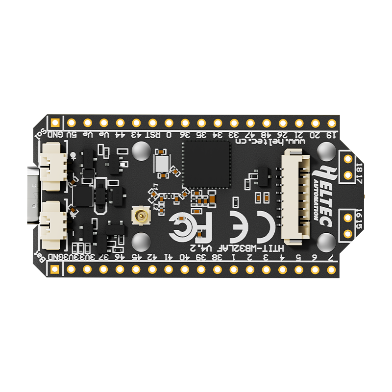
The LoRa 32 V4 is a versatile microcontroller board equipped with a built-in LoRa (Long Range) radio module. It is specifically designed for low-power wireless communication over long distances, making it an excellent choice for Internet of Things (IoT) applications. The board combines the power of a microcontroller with the capabilities of LoRa technology, enabling seamless data transmission in remote or hard-to-reach areas.
Explore Projects Built with LoRa 32 V4
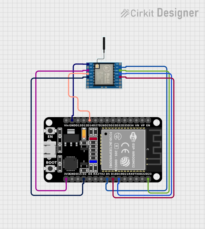

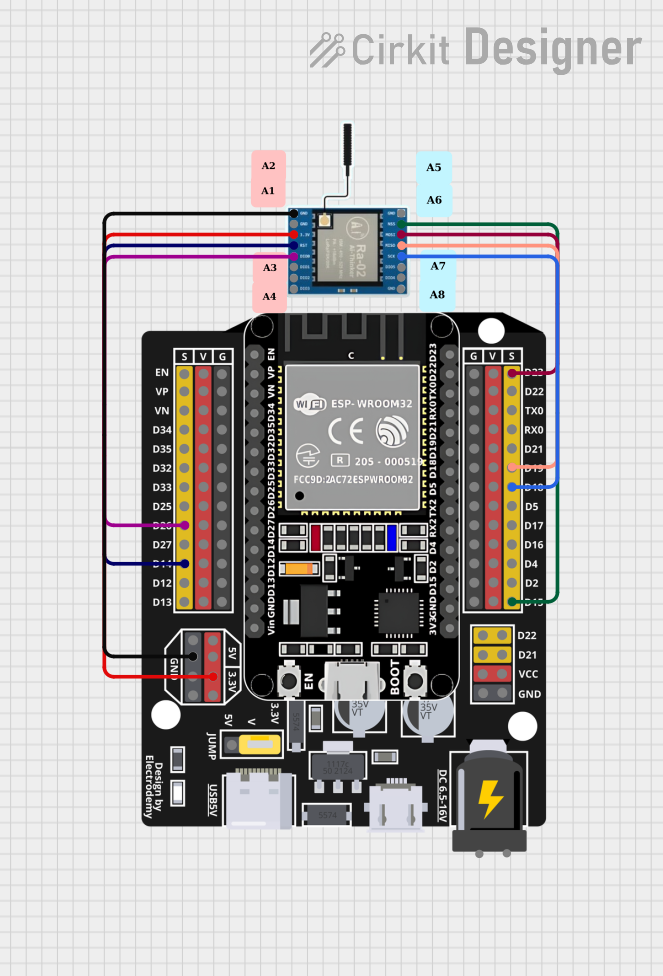

Explore Projects Built with LoRa 32 V4
Common Applications and Use Cases
- Smart agriculture (e.g., soil moisture monitoring, weather stations)
- Industrial IoT (e.g., asset tracking, predictive maintenance)
- Smart cities (e.g., parking sensors, air quality monitoring)
- Home automation and security systems
- Remote environmental monitoring
- Long-range wireless sensor networks
Technical Specifications
The LoRa 32 V4 board is built to provide robust performance for a wide range of applications. Below are its key technical details:
Key Technical Details
| Parameter | Specification |
|---|---|
| Microcontroller | ESP32 (dual-core, 32-bit processor) |
| LoRa Module | Semtech SX1276 |
| Operating Voltage | 3.3V |
| Input Voltage Range | 5V (via USB) or 3.7V (via LiPo battery) |
| Flash Memory | 4MB |
| SRAM | 520KB |
| Frequency Band | 433MHz / 868MHz / 915MHz (region-specific) |
| Communication Protocols | LoRa, SPI, I2C, UART, Wi-Fi, Bluetooth |
| Antenna Connector | IPEX (external antenna required) |
| Power Consumption | Ultra-low power in sleep mode |
| Dimensions | 51mm x 25mm |
Pin Configuration and Descriptions
The LoRa 32 V4 board features a variety of pins for interfacing with external components. Below is the pinout description:
| Pin Name | Function | Description |
|---|---|---|
| 3V3 | Power Output | Provides 3.3V output for external components. |
| GND | Ground | Common ground for the circuit. |
| VIN | Power Input | Accepts 5V input via USB or 3.7V via LiPo. |
| GPIO0 | General Purpose I/O | Used for programming and boot mode selection. |
| GPIO21 | I2C SDA | Data line for I2C communication. |
| GPIO22 | I2C SCL | Clock line for I2C communication. |
| GPIO16 | LoRa Reset | Resets the LoRa module. |
| GPIO17 | LoRa DIO1 | Digital I/O for LoRa module. |
| GPIO18 | SPI SCK | Clock line for SPI communication. |
| GPIO19 | SPI MISO | Master In Slave Out for SPI communication. |
| GPIO23 | SPI MOSI | Master Out Slave In for SPI communication. |
| GPIO5 | LoRa NSS | Chip select for LoRa module. |
| EN | Enable | Enables or disables the board. |
| BAT | Battery Voltage | Monitors the voltage of the connected battery. |
Usage Instructions
The LoRa 32 V4 board is easy to integrate into your projects. Follow the steps below to get started:
How to Use the Component in a Circuit
- Power the Board: Connect the board to a 5V USB power source or a 3.7V LiPo battery.
- Connect the Antenna: Attach an external antenna to the IPEX connector for optimal LoRa performance.
- Program the Board: Use the Arduino IDE or other compatible software to upload your code. Ensure the correct board and port are selected in the IDE.
- Interface with Sensors/Actuators: Use the GPIO, I2C, or SPI pins to connect external components.
- Establish LoRa Communication: Configure the LoRa module for the desired frequency and communication settings.
Important Considerations and Best Practices
- Antenna Placement: Ensure the antenna is securely connected and positioned away from interference sources.
- Power Supply: Use a stable power source to avoid voltage fluctuations that may affect performance.
- Frequency Compliance: Verify that the selected frequency band complies with local regulations.
- Sleep Mode: Utilize the board's low-power sleep mode to extend battery life in IoT applications.
- Heat Management: Avoid placing the board in enclosed spaces without ventilation, as the ESP32 may generate heat during operation.
Example Code for Arduino UNO
Below is an example of how to send a simple message using the LoRa 32 V4 board with the Arduino IDE:
#include <SPI.h>
#include <LoRa.h>

// Define LoRa module pins
#define LORA_SCK 18
#define LORA_MISO 19
#define LORA_MOSI 23
#define LORA_SS 5
#define LORA_RST 16
#define LORA_DIO0 17

void setup() {
  // Initialize serial communication
  Serial.begin(9600);
  while (!Serial);

  // Initialize LoRa module
  Serial.println("Initializing LoRa...");
  LoRa.setPins(LORA_SS, LORA_RST, LORA_DIO0);
  if (!LoRa.begin(915E6)) { // Set frequency to 915 MHz
    Serial.println("LoRa initialization failed!");
    while (1);
  }
  Serial.println("LoRa initialized successfully.");
}

void loop() {
  // Send a message
  Serial.println("Sending message...");
  LoRa.beginPacket();
  LoRa.print("Hello, LoRa!");
  LoRa.endPacket();

  // Wait for 5 seconds before sending the next message
  delay(5000);
}
Troubleshooting and FAQs
Common Issues Users Might Face
LoRa Module Not Initializing:
- Cause: Incorrect wiring or frequency mismatch.
- Solution: Double-check the wiring and ensure the frequency matches your region's regulations.
No Data Transmission:
- Cause: Antenna not connected or poor signal strength.
- Solution: Verify the antenna connection and ensure there are no obstructions between devices.
Board Not Detected by Arduino IDE:
- Cause: Missing drivers or incorrect board selection.
- Solution: Install the required USB drivers and select "ESP32 Dev Module" in the Arduino IDE.
High Power Consumption:
- Cause: Board not in sleep mode during idle periods.
- Solution: Implement sleep mode in your code to reduce power usage.
Solutions and Tips for Troubleshooting
- Use a multimeter to check the voltage levels at the power pins.
- Test the board with a simple "blink" sketch to ensure the microcontroller is functioning.
- Update the LoRa and ESP32 libraries in the Arduino IDE to the latest versions.
- If the board overheats, reduce the workload or improve ventilation.
By following this documentation, you can effectively utilize the LoRa 32 V4 board in your projects and troubleshoot common issues with ease.