How to Use PowerBoost 1000 Basic JST Terminal: Examples, Pinouts, and Specs
Introduction
The PowerBoost 1000 Basic JST Terminal is a versatile and compact power supply module designed to boost battery voltages to a stable 5V output, capable of delivering up to 1A of current. This makes it an ideal choice for powering 5V electronics from a lower voltage source, such as a single-cell LiPo battery. Common applications include portable USB chargers, battery-powered electronics, and DIY projects where a stable 5V power supply is required.
Explore Projects Built with PowerBoost 1000 Basic JST Terminal
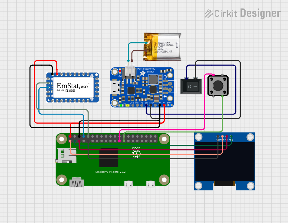
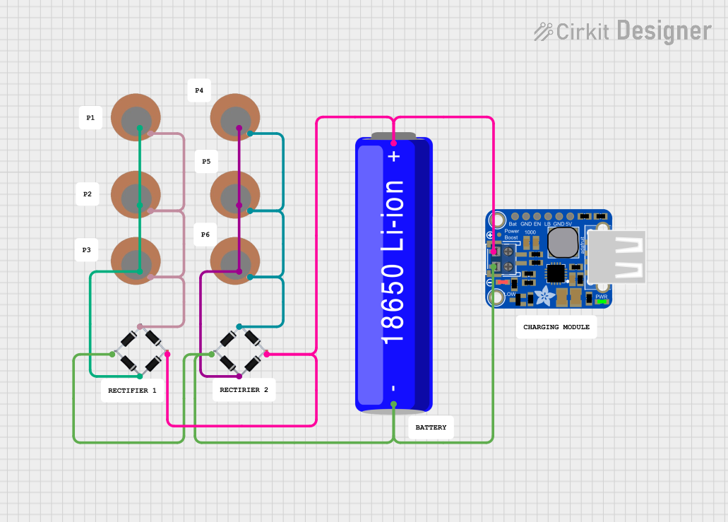


Explore Projects Built with PowerBoost 1000 Basic JST Terminal
Technical Specifications
Key Technical Details
- Input Voltage: 1.8V to 5.5V
- Output Voltage: 5V regulated
- Output Current: Up to 1A
- Efficiency: 90% typical at full load
- Quiescent Current: 5mA typical
- Switching Frequency: 1.2MHz
- Operating Temperature: -40°C to +85°C
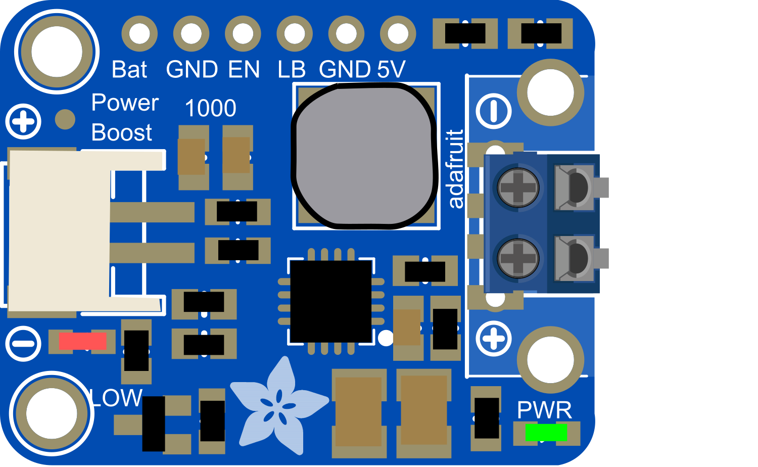
Pin Configuration and Descriptions
| Pin Name | Description |
|---|---|
| VIN | Input voltage (1.8V to 5.5V) |
| GND | Ground connection |
| 5V | Regulated 5V output |
| EN | Enable pin (active high) |
| BAT | Battery connection for monitoring |
Usage Instructions
Connecting the PowerBoost 1000 Basic
- Power Input: Connect your power source (e.g., a LiPo battery) to the VIN and GND pins. Ensure the voltage is within the specified range.
- Power Output: Connect your 5V device to the 5V and GND output terminals.
- Enable Pin: If you wish to control the power state of the module, connect the EN pin to a digital output on your microcontroller. Drive it high to enable the output or low to disable it.
Best Practices
- Heat Management: When drawing high currents, ensure the module is well-ventilated as it may generate heat.
- Input Voltage: Do not exceed the recommended input voltage range to prevent damage.
- Battery Monitoring: Use the BAT pin to monitor the battery voltage if necessary.
- Short Circuit Protection: Always include a fuse or current limiting device to protect against short circuits.
Example Code for Arduino UNO
// Example code to enable and disable the PowerBoost 1000 Basic using an Arduino UNO

const int enablePin = 7; // Connect the EN pin of PowerBoost to digital pin 7

void setup() {
  pinMode(enablePin, OUTPUT); // Set the enable pin as an output
}

void loop() {
  digitalWrite(enablePin, HIGH); // Enable the PowerBoost
  delay(5000);                  // Wait for 5 seconds
  digitalWrite(enablePin, LOW);  // Disable the PowerBoost
  delay(5000);                  // Wait for 5 seconds
}
Troubleshooting and FAQs
Common Issues
- No Output Voltage: Ensure the input voltage is within the specified range and connections are secure.
- Output Voltage Drops Under Load: This may occur if the input power source cannot supply enough current. Check the power source's specifications.
- Module Overheating: Reduce the load or improve ventilation around the module.
FAQs
Q: Can I use the PowerBoost 1000 Basic to charge my phone? A: Yes, as long as your phone charges via 5V and the current draw is within 1A.
Q: What type of battery should I use with the PowerBoost 1000 Basic? A: A single-cell LiPo battery is recommended for optimal performance.
Q: Can I use multiple PowerBoost 1000 Basics in parallel for more current? A: It is not recommended to use boost converters in parallel due to potential issues with load sharing and synchronization.
Q: How can I monitor the battery level? A: You can connect the BAT pin to an analog input on your microcontroller to monitor the battery voltage.
For further assistance or more complex issues, please contact the manufacturer's support team.