Cirkit Designer Logo
Cirkit Designer
Your all-in-one circuit design IDE
Home / 
Component Documentation

How to Use Ideal Diode: Examples, Pinouts, and Specs

Image of Ideal Diode
Cirkit Designer LogoDesign with Ideal Diode in Cirkit Designer

Introduction

An Ideal Diode is a theoretical electronic component that exhibits perfect diode behavior. It allows current to flow in one direction without any resistance or voltage drop when forward-biased, and completely blocks current in the reverse direction. Unlike real-world diodes, which have a small forward voltage drop and leakage current, the ideal diode is a conceptual model used to simplify circuit analysis and design.

Explore Projects Built with Ideal Diode

Use Cirkit Designer to design, explore, and prototype these projects online. Some projects support real-time simulation. Click "Open Project" to start designing instantly!
Rectifier Diode and LED Circuit with Rocker Switch Control
Image of hypihygi innovations: A project utilizing Ideal Diode in a practical application
This circuit appears to be a simple power supply circuit with a protection diode and an LED indicator. The diode ensures current flows in only one direction, protecting the circuit from reverse polarity damage. A rocker switch is used to control the power to the LED, which likely serves as an indicator for when the power is on.
Cirkit Designer LogoOpen Project in Cirkit Designer
AC Power Supply with Diode Rectification and Bulb Indicator
Image of susa: A project utilizing Ideal Diode in a practical application
This circuit is a simple AC-powered light with a diode in series. The diode is connected in series with the AC supply's positive terminal and the AC bulb's neutral terminal, while the bulb's positive terminal is connected to the AC supply's negative terminal. The diode will rectify the AC current, allowing only one half of the AC waveform to pass through to the bulb, causing it to flicker at a rate of half the AC frequency.
Cirkit Designer LogoOpen Project in Cirkit Designer
12V to 5V Power Supply with LED Indicator and Push Switch
Image of Power Supply LVCO: A project utilizing Ideal Diode in a practical application
This circuit is a 12V to 5V regulated power supply with an LED indicator. It uses a 5408 diode for reverse polarity protection, an LM340T5 7805 voltage regulator to step down the voltage to 5V, and a push switch to control the LED indicator. The circuit also includes capacitors for filtering and a resistor to limit the current through the LED.
Cirkit Designer LogoOpen Project in Cirkit Designer
Arduino Nano-Based Light Sensing Circuit with LED Indicator
Image of Copy of LED yellow 2 pin mood light: A project utilizing Ideal Diode in a practical application
This circuit is designed to measure light intensity using a photodiode and a resistor to create a voltage divider, with the signal read by the Arduino Nano's A0 pin. A yellow LED is connected to the D2 pin, potentially serving as an indicator. The 9V battery powers the circuit, and the Arduino's code is yet to be implemented for specific functionality.
Cirkit Designer LogoOpen Project in Cirkit Designer

Explore Projects Built with Ideal Diode

Use Cirkit Designer to design, explore, and prototype these projects online. Some projects support real-time simulation. Click "Open Project" to start designing instantly!
Image of hypihygi innovations: A project utilizing Ideal Diode in a practical application
Rectifier Diode and LED Circuit with Rocker Switch Control
This circuit appears to be a simple power supply circuit with a protection diode and an LED indicator. The diode ensures current flows in only one direction, protecting the circuit from reverse polarity damage. A rocker switch is used to control the power to the LED, which likely serves as an indicator for when the power is on.
Cirkit Designer LogoOpen Project in Cirkit Designer
Image of susa: A project utilizing Ideal Diode in a practical application
AC Power Supply with Diode Rectification and Bulb Indicator
This circuit is a simple AC-powered light with a diode in series. The diode is connected in series with the AC supply's positive terminal and the AC bulb's neutral terminal, while the bulb's positive terminal is connected to the AC supply's negative terminal. The diode will rectify the AC current, allowing only one half of the AC waveform to pass through to the bulb, causing it to flicker at a rate of half the AC frequency.
Cirkit Designer LogoOpen Project in Cirkit Designer
Image of Power Supply LVCO: A project utilizing Ideal Diode in a practical application
12V to 5V Power Supply with LED Indicator and Push Switch
This circuit is a 12V to 5V regulated power supply with an LED indicator. It uses a 5408 diode for reverse polarity protection, an LM340T5 7805 voltage regulator to step down the voltage to 5V, and a push switch to control the LED indicator. The circuit also includes capacitors for filtering and a resistor to limit the current through the LED.
Cirkit Designer LogoOpen Project in Cirkit Designer
Image of Copy of LED yellow 2 pin mood light: A project utilizing Ideal Diode in a practical application
Arduino Nano-Based Light Sensing Circuit with LED Indicator
This circuit is designed to measure light intensity using a photodiode and a resistor to create a voltage divider, with the signal read by the Arduino Nano's A0 pin. A yellow LED is connected to the D2 pin, potentially serving as an indicator. The 9V battery powers the circuit, and the Arduino's code is yet to be implemented for specific functionality.
Cirkit Designer LogoOpen Project in Cirkit Designer

Common Applications and Use Cases

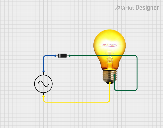
  • Rectification: Converting AC to DC in power supplies.
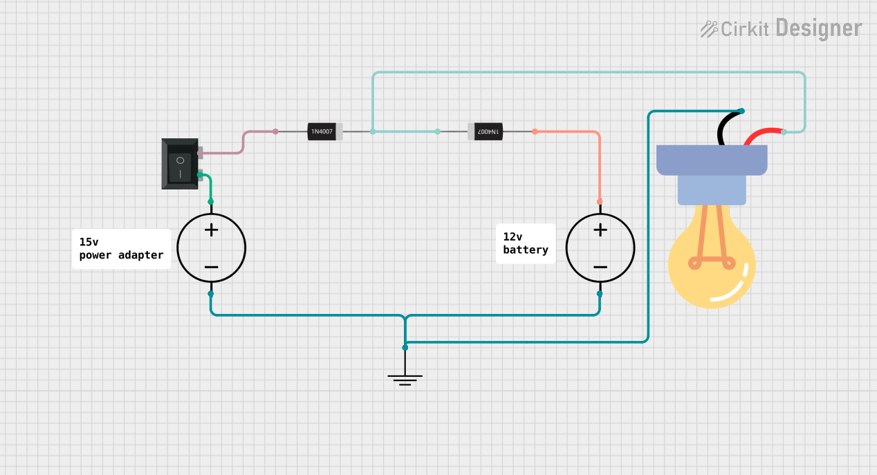
  • Reverse Polarity Protection: Preventing damage to circuits caused by incorrect power supply connections.
  • Voltage Clamping: Protecting sensitive components from voltage spikes.
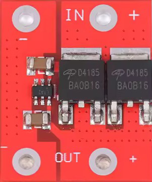
  • Ideal Diode Controllers: Used in power management systems to mimic ideal diode behavior.

Technical Specifications

Since the ideal diode is a theoretical component, it does not have physical specifications like real diodes. However, its behavior can be approximated using real-world components such as Schottky diodes or MOSFET-based ideal diode controllers.

Key Characteristics

Parameter Value
Forward Voltage Drop 0 V
Reverse Leakage Current 0 A
Forward Current Unlimited (theoretically)
Reverse Voltage Infinite (theoretically)

Pin Configuration and Descriptions

The ideal diode is represented symbolically in circuits. Below is the pin configuration:

Pin Name Description
Anode Positive terminal; current enters here when forward-biased.
Cathode Negative terminal; current exits here when forward-biased.

Usage Instructions

How to Use the Ideal Diode in a Circuit

  1. Forward Bias Operation: Connect the anode to the positive side of the circuit and the cathode to the negative side. In this configuration, the ideal diode will conduct current without any resistance or voltage drop.
  2. Reverse Bias Operation: If the cathode is at a higher potential than the anode, the ideal diode will block all current flow, acting as an open circuit.

Important Considerations and Best Practices

  • Simulation Use: Ideal diodes are often used in circuit simulations to simplify analysis. In real-world applications, use components like Schottky diodes or MOSFET-based controllers to approximate ideal behavior.
  • Thermal Management: While the ideal diode does not generate heat, real-world approximations will have power losses due to forward voltage drops. Ensure proper heat dissipation in high-current applications.
  • Parasitic Effects: Real diodes have capacitance and inductance, which can affect high-frequency performance. These effects are absent in the ideal diode model.

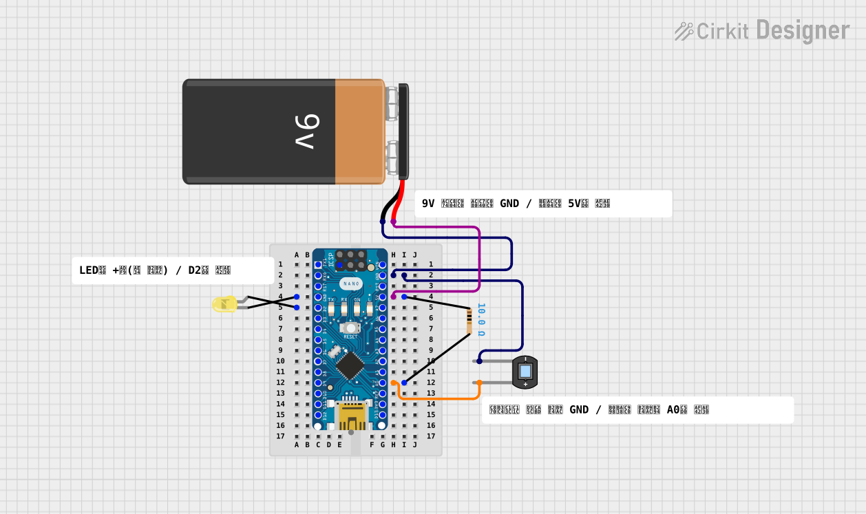
Example: Using an Ideal Diode with an Arduino UNO

While the ideal diode itself is not a physical component, you can simulate its behavior using a Schottky diode or an ideal diode controller. Below is an example of using a Schottky diode for reverse polarity protection in an Arduino UNO circuit:

Circuit Description

  • The Schottky diode is placed between the power supply and the Arduino UNO's VIN pin to prevent damage from reverse polarity.

Code Example

// Example code for Arduino UNO to demonstrate basic functionality
// of a circuit protected by a Schottky diode (ideal diode approximation).

void setup() {
  pinMode(13, OUTPUT); // Set pin 13 as an output for the onboard LED
}

void loop() {
  digitalWrite(13, HIGH); // Turn the LED on
  delay(1000);            // Wait for 1 second
  digitalWrite(13, LOW);  // Turn the LED off
  delay(1000);            // Wait for 1 second
}

// Note: The Schottky diode in the circuit ensures that the Arduino
// is protected from reverse polarity damage. This code assumes
// the power supply is connected correctly.

Troubleshooting and FAQs

Common Issues Users Might Face

  1. No Current Flow in Forward Bias:

    • Cause: Incorrect connection of the anode and cathode.
    • Solution: Verify that the anode is connected to the positive terminal and the cathode to the negative terminal.
  2. Unexpected Voltage Drop:

    • Cause: Using a real diode instead of an ideal diode.
    • Solution: Use a low forward voltage drop diode, such as a Schottky diode, to approximate ideal behavior.
  3. Circuit Malfunction in Reverse Bias:

    • Cause: Leakage current in real diodes.
    • Solution: Use a diode with minimal reverse leakage current or an ideal diode controller.

Solutions and Tips for Troubleshooting

  • Simulations: Use circuit simulation software (e.g., LTspice, Multisim) to test ideal diode behavior before implementing real-world circuits.
  • Component Selection: For real-world applications, choose diodes with characteristics that closely match the ideal diode model.
  • Testing: Use a multimeter to verify the forward and reverse bias behavior of the diode in your circuit.

By understanding the theoretical behavior of the ideal diode and its practical approximations, you can design efficient and reliable circuits for a wide range of applications.