
How to Use Logic level 3,3V-5V step-up (4 channels, SPI/UART): Examples, Pinouts, and Specs
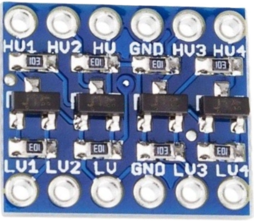
 Design with Logic level 3,3V-5V step-up (4 channels, SPI/UART) in Cirkit Designer
Introduction
The Logic Level 3.3V-5V Step-Up (4 Channels, SPI/UART), manufactured by JH Global Trading (HK) Co., Limited, is a versatile bidirectional logic level converter. It allows seamless communication between devices operating at different voltage levels, specifically stepping up signals from 3.3V to 5V or stepping down from 5V to 3.3V. This component is particularly useful in interfacing microcontrollers, sensors, and communication modules that operate at different logic levels.
Explore Projects Built with Logic level 3,3V-5V step-up (4 channels, SPI/UART)
 Open Project in Cirkit Designer
 Open Project in Cirkit Designer
 Open Project in Cirkit Designer
 Open Project in Cirkit Designer
Explore Projects Built with Logic level 3,3V-5V step-up (4 channels, SPI/UART)
Open Project in Cirkit DesignerOpen Project in Cirkit DesignerOpen Project in Cirkit DesignerOpen Project in Cirkit DesignerCommon Applications and Use Cases
- Interfacing 3.3V microcontrollers (e.g., ESP32, Raspberry Pi) with 5V peripherals (e.g., Arduino, sensors).
- Bridging communication between UART, SPI, or I2C devices with differing voltage levels.
- Ensuring signal integrity and compatibility in mixed-voltage systems.
- Prototyping and development of embedded systems.
Technical Specifications
Below are the key technical details for the Logic Level 3.3V-5V Step-Up (4 Channels, SPI/UART):
| Parameter | Value |
|---|---|
| Operating Voltage (Low) | 3.3V |
| Operating Voltage (High) | 5V |
| Number of Channels | 4 |
| Communication Protocols | SPI, UART, I2C (bidirectional) |
| Maximum Data Rate | 10 Mbps (SPI/UART) |
| Current Consumption | < 1 mA |
| Operating Temperature | -40°C to +85°C |
| Dimensions | 15mm x 12mm x 3mm |
Pin Configuration and Descriptions
The component has a total of 8 pins, as described in the table below:
| Pin | Name | Description |
|---|---|---|
| 1 | HV | High voltage input (5V). Connect to the 5V power supply. |
| 2 | LV | Low voltage input (3.3V). Connect to the 3.3V power supply. |
| 3 | GND | Ground. Common ground for both voltage levels. |
| 4 | HV1 | High voltage signal channel 1. Connect to the 5V device signal line. |
| 5 | LV1 | Low voltage signal channel 1. Connect to the 3.3V device signal line. |
| 6 | HV2 | High voltage signal channel 2. Connect to the 5V device signal line. |
| 7 | LV2 | Low voltage signal channel 2. Connect to the 3.3V device signal line. |
| 8 | GND | Additional ground pin for improved stability. |
Usage Instructions
How to Use the Component in a Circuit
Power Connections:
- Connect the HV pin to a 5V power supply.
- Connect the LV pin to a 3.3V power supply.
- Ensure both devices share a common ground by connecting the GND pins.
Signal Connections:
- For each channel, connect the high-voltage signal line (e.g., from a 5V device) to the corresponding HVx pin.
- Connect the low-voltage signal line (e.g., from a 3.3V device) to the corresponding LVx pin.
- Repeat for all required channels (up to 4).
Communication Protocols:
- The component supports SPI, UART, and I2C protocols. Ensure proper wiring and configuration of the communication lines.
Important Considerations and Best Practices
- Voltage Compatibility: Ensure the connected devices operate at 3.3V and 5V logic levels. Do not exceed these voltage limits.
- Data Rate: For high-speed communication (e.g., SPI), keep the wiring short to minimize signal degradation.
- Grounding: Proper grounding is critical for stable operation. Use a single common ground for all devices in the circuit.
- Unused Channels: Leave unused channels unconnected or tie them to ground to avoid noise interference.
Example: Connecting to an Arduino UNO
Below is an example of using the logic level converter to interface a 3.3V sensor with an Arduino UNO (5V logic):
Circuit Diagram
- HV: Connect to Arduino UNO's 5V pin.
- LV: Connect to the sensor's 3.3V pin.
- GND: Connect to the common ground.
- HV1: Connect to Arduino's digital pin (e.g., D2).
- LV1: Connect to the sensor's data pin.
Arduino Code Example
// Example: Reading data from a 3.3V sensor using a logic level converter
// Ensure proper wiring as per the circuit diagram above.

#define SENSOR_PIN 2  // Arduino pin connected to HV1 (via the converter)

void setup() {
  pinMode(SENSOR_PIN, INPUT);  // Set the pin as input
  Serial.begin(9600);          // Initialize serial communication
}

void loop() {
  int sensorValue = digitalRead(SENSOR_PIN);  // Read the sensor value
  Serial.println(sensorValue);                // Print the value to the Serial Monitor
  delay(500);                                 // Wait for 500ms
}
Troubleshooting and FAQs
Common Issues and Solutions
No Signal Transmission:
- Cause: Incorrect power supply connections.
- Solution: Verify that the HV and LV pins are connected to 5V and 3.3V, respectively.
Signal Distortion or Noise:
- Cause: Long wires or poor grounding.
- Solution: Use shorter wires and ensure a solid common ground connection.
Communication Failure:
- Cause: Incorrect wiring of communication lines.
- Solution: Double-check the connections for SPI, UART, or I2C lines.
Overheating:
- Cause: Exceeding voltage or current limits.
- Solution: Ensure the connected devices operate within the specified voltage and current ratings.
FAQs
Q1: Can this component step down 5V signals to 3.3V?
A1: Yes, the component is bidirectional and can step down 5V signals to 3.3V as well as step up 3.3V signals to 5V.
Q2: Can I use this for I2C communication?
A2: Yes, the component supports I2C communication. Ensure proper pull-up resistors are used on the I2C lines.
Q3: What is the maximum data rate supported?
A3: The component supports data rates up to 10 Mbps, making it suitable for most SPI and UART applications.
Q4: Can I use this with a 1.8V device?
A4: No, this component is designed specifically for 3.3V and 5V logic levels. For 1.8V devices, a different level shifter is required.