
How to Use PN532: Examples, Pinouts, and Specs
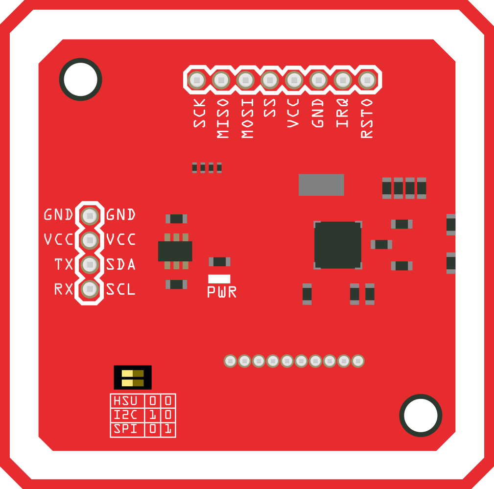
 Design with PN532 in Cirkit Designer
Introduction
The PN532, manufactured by Elechouse, is a versatile NFC (Near Field Communication) controller designed to enable seamless communication with NFC-enabled devices. It supports multiple modes of operation, including reader/writer, card emulation, and peer-to-peer communication. This makes it an ideal choice for a wide range of applications such as contactless payments, access control, and data exchange.
The PN532 is widely used in embedded systems and IoT projects due to its compatibility with microcontrollers like Arduino and Raspberry Pi. Its robust design and support for various NFC protocols make it a reliable and efficient solution for NFC-based applications.
Explore Projects Built with PN532
 Open Project in Cirkit Designer
 Open Project in Cirkit Designer
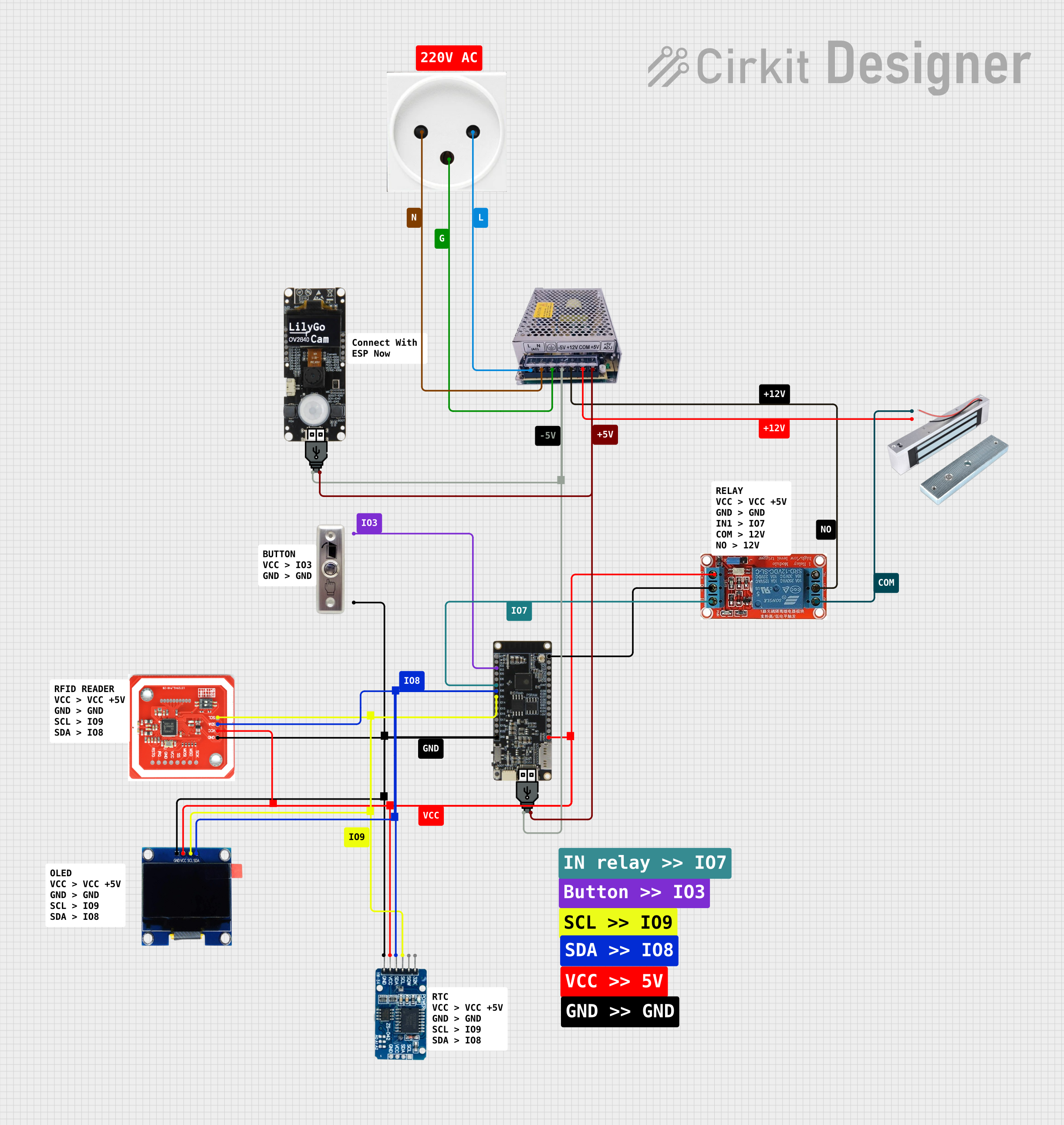 Open Project in Cirkit Designer
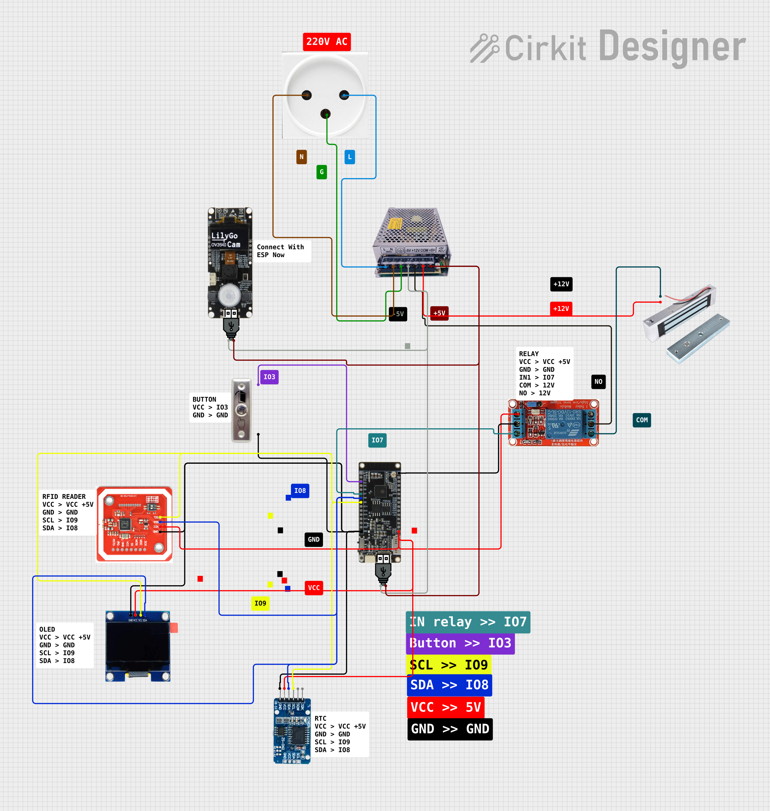 Open Project in Cirkit Designer
Explore Projects Built with PN532
Open Project in Cirkit DesignerOpen Project in Cirkit DesignerOpen Project in Cirkit DesignerOpen Project in Cirkit DesignerTechnical Specifications
Below are the key technical details and pin configuration of the PN532 module:
Key Technical Details
| Parameter | Value |
|---|---|
| Manufacturer | Elechouse |
| Part ID | PN532 |
| Communication Protocols | I2C, SPI, UART |
| Operating Voltage | 3.3V to 5V |
| Current Consumption | ~50mA (active mode) |
| NFC Standards Supported | ISO/IEC 14443 Type A & B, FeliCa, NFC-IP1 |
| Operating Frequency | 13.56 MHz |
| Operating Modes | Reader/Writer, Card Emulation, P2P |
| Detection Range | Up to 5 cm (depending on antenna design) |
| Dimensions | ~40mm x 40mm |
Pin Configuration and Descriptions
The PN532 module typically comes with an 8-pin header. Below is the pinout and description:
| Pin Number | Pin Name | Description |
|---|---|---|
| 1 | VCC | Power supply input (3.3V to 5V). |
| 2 | GND | Ground connection. |
| 3 | SDA/MOSI | I2C data line (SDA) or SPI MOSI (Master Out Slave In) line. |
| 4 | SCL/SCK | I2C clock line (SCL) or SPI clock (SCK) line. |
| 5 | IRQ | Interrupt request pin, used for signaling events to the microcontroller. |
| 6 | RSTPD | Reset and power-down pin. Active low to reset the module. |
| 7 | TXD | UART transmit pin, used for serial communication. |
| 8 | RXD | UART receive pin, used for serial communication. |
Usage Instructions
The PN532 can be used in various configurations depending on the communication protocol (I2C, SPI, or UART). Below are the steps to use the PN532 module in a circuit and some best practices:
Connecting the PN532 to an Arduino UNO (I2C Mode)
Wiring:
- Connect the
VCCpin of the PN532 to the5Vpin on the Arduino UNO. - Connect the
GNDpin of the PN532 to theGNDpin on the Arduino UNO. - Connect the
SDApin of the PN532 to theA4pin on the Arduino UNO. - Connect the
SCLpin of the PN532 to theA5pin on the Arduino UNO.
- Connect the
Install Required Libraries:
- Download and install the "Adafruit_PN532" library from the Arduino Library Manager.
Example Code: Below is an example Arduino sketch to read an NFC tag using the PN532 in I2C mode:
#include <Wire.h>
#include <Adafruit_PN532.h>

// Define the I2C pins for the PN532
#define SDA_PIN A4
#define SCL_PIN A5

// Create an instance of the Adafruit_PN532 class
Adafruit_PN532 nfc(SDA_PIN, SCL_PIN);

void setup() {
  Serial.begin(9600); // Initialize serial communication
  Serial.println("Initializing PN532...");

  nfc.begin(); // Initialize the PN532 module

  uint32_t versiondata = nfc.getFirmwareVersion();
  if (!versiondata) {
    Serial.println("Didn't find PN532 board");
    while (1); // Halt the program if the module is not detected
  }

  // Display firmware version
  Serial.print("Found PN532 with firmware version: ");
  Serial.print((versiondata >> 16) & 0xFF, HEX);
  Serial.print('.');
  Serial.println((versiondata >> 8) & 0xFF, HEX);

  nfc.SAMConfig(); // Configure the module to read NFC tags
  Serial.println("Waiting for an NFC tag...");
}

void loop() {
  uint8_t success;
  uint8_t uid[] = { 0, 0, 0, 0, 0, 0, 0 }; // Buffer to store the UID
  uint8_t uidLength; // Length of the UID

  // Try to read an NFC tag
  success = nfc.readPassiveTargetID(PN532_MIFARE_ISO14443A, uid, &uidLength);

  if (success) {
    Serial.println("NFC tag detected!");
    Serial.print("UID Length: "); Serial.print(uidLength, DEC); Serial.println(" bytes");
    Serial.print("UID Value: ");
    for (uint8_t i = 0; i < uidLength; i++) {
      Serial.print(" 0x"); Serial.print(uid[i], HEX);
    }
    Serial.println();
    delay(1000); // Wait 1 second before scanning again
  }
}
Best Practices
- Ensure the power supply voltage matches the module's requirements (3.3V to 5V).
- Use appropriate pull-up resistors for I2C communication if not already included on the module.
- Avoid placing the module near metal objects or other sources of electromagnetic interference, as this can reduce NFC performance.
- Use a stable power source to prevent communication errors.
Troubleshooting and FAQs
Common Issues
PN532 Not Detected:
- Cause: Incorrect wiring or communication protocol mismatch.
- Solution: Double-check the wiring and ensure the correct protocol (I2C, SPI, or UART) is selected in the code.
NFC Tag Not Detected:
- Cause: Tag is out of range or incompatible with the PN532.
- Solution: Ensure the tag is within 5 cm of the antenna and supports ISO/IEC 14443 Type A or B.
Intermittent Communication Errors:
- Cause: Unstable power supply or noisy environment.
- Solution: Use a decoupling capacitor near the module and ensure a clean power source.
FAQs
Can the PN532 read all types of NFC tags?
- The PN532 supports ISO/IEC 14443 Type A & B, FeliCa, and NFC-IP1 standards. Ensure your tag complies with these standards.
What is the maximum range of the PN532?
- The detection range is up to 5 cm, depending on the antenna design and environmental factors.
Can the PN532 be used for peer-to-peer communication?
- Yes, the PN532 supports peer-to-peer (P2P) communication for data exchange between two NFC-enabled devices.
By following this documentation, users can effectively integrate the PN532 into their projects and troubleshoot common issues.