How to Use HB100 10.525 GHz Doppler Sensor: Examples, Pinouts, and Specs
Introduction
The HB100 is a microwave Doppler radar sensor that operates at a frequency of 10.525 GHz. It is designed for motion detection and speed measurement by utilizing the Doppler effect. This compact and efficient sensor can detect the presence and movement of objects, making it ideal for a wide range of applications, including:
- Security systems for motion detection
- Automatic door openers
- Traffic monitoring and speed measurement
- Industrial automation and robotics
- Smart home systems
The HB100 is a versatile and reliable component, offering high sensitivity and low power consumption, making it suitable for both hobbyist and professional projects.
Explore Projects Built with HB100 10.525 GHz Doppler Sensor


Explore Projects Built with HB100 10.525 GHz Doppler Sensor
Technical Specifications
Key Technical Details
| Parameter | Value |
|---|---|
| Operating Frequency | 10.525 GHz |
| Operating Voltage | 4.75V to 5.25V DC |
| Operating Current | 30 mA (typical) |
| Output Signal | Analog IF signal (Doppler) |
| Detection Range | Up to 20 meters (depending on target size and environment) |
| Beam Angle | 80° (horizontal), 34° (vertical) |
| Operating Temperature | -20°C to +75°C |
| Dimensions | 46 mm x 38 mm x 8 mm |
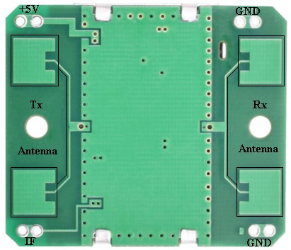
Pin Configuration and Descriptions
The HB100 sensor has a 4-pin interface. The pin configuration is as follows:
| Pin Number | Pin Name | Description |
|---|---|---|
| 1 | IF Output | Intermediate frequency (Doppler signal output) |
| 2 | GND | Ground connection |
| 3 | VCC | Power supply (4.75V to 5.25V DC) |
| 4 | NC | Not connected (leave unconnected) |
Usage Instructions
How to Use the HB100 in a Circuit
- Power Supply: Connect the VCC pin to a 5V DC power source and the GND pin to the ground of your circuit.
- Signal Output: The IF Output pin provides an analog signal corresponding to the Doppler shift caused by moving objects. This signal can be amplified and processed using an operational amplifier or a microcontroller with an ADC (Analog-to-Digital Converter).
- Amplification and Filtering: Since the output signal is weak, it is recommended to use an amplifier circuit to boost the signal. Additionally, a low-pass filter can be used to remove noise.
- Microcontroller Interface: The amplified signal can be fed into a microcontroller (e.g., Arduino UNO) for further processing, such as detecting motion or calculating speed.
Important Considerations and Best Practices
- Mounting: Ensure the sensor is mounted securely and oriented correctly for optimal detection. Avoid placing it near metal objects that may interfere with the signal.
- Environment: The detection range and accuracy may vary depending on environmental factors such as temperature, humidity, and obstacles.
- Signal Processing: Use appropriate signal processing techniques to extract meaningful data from the Doppler signal.
- Power Supply: Use a stable 5V power source to ensure reliable operation.
Example: Connecting the HB100 to an Arduino UNO
Below is an example of how to connect the HB100 to an Arduino UNO and process the Doppler signal:
Circuit Connections
- Connect the VCC pin of the HB100 to the 5V pin of the Arduino.
- Connect the GND pin of the HB100 to the GND pin of the Arduino.
- Connect the IF Output pin of the HB100 to an analog input pin (e.g., A0) of the Arduino.
Arduino Code
// HB100 Doppler Sensor Example with Arduino UNO
// This code reads the analog signal from the HB100 and prints the values
// to the Serial Monitor for analysis.

const int sensorPin = A0; // Pin connected to the IF Output of the HB100

void setup() {
  Serial.begin(9600); // Initialize serial communication at 9600 baud
  pinMode(sensorPin, INPUT); // Set the sensor pin as input
}

void loop() {
  int sensorValue = analogRead(sensorPin); // Read the analog value from the sensor
  Serial.println(sensorValue); // Print the value to the Serial Monitor

  delay(100); // Delay for 100ms to reduce the frequency of readings
}
Notes on the Code
- The analog values printed to the Serial Monitor represent the Doppler signal. You can analyze these values to detect motion or calculate speed.
- For speed measurement, you will need to perform additional signal processing to calculate the frequency of the Doppler signal.
Troubleshooting and FAQs
Common Issues and Solutions
No Output Signal:
- Ensure the sensor is powered correctly (check VCC and GND connections).
- Verify that the target object is within the detection range and moving.
Weak or Noisy Signal:
- Use an amplifier circuit to boost the signal strength.
- Add a low-pass filter to reduce noise.
Interference from Nearby Objects:
- Avoid placing the sensor near large metal objects or other RF-emitting devices.
- Ensure the sensor has a clear line of sight to the target.
Inconsistent Readings:
- Check for environmental factors such as temperature changes or obstacles.
- Ensure the power supply is stable and free from fluctuations.
FAQs
Q: Can the HB100 detect stationary objects?
A: No, the HB100 relies on the Doppler effect, which requires relative motion between the sensor and the object.
Q: What is the maximum detection range of the HB100?
A: The detection range is up to 20 meters, depending on the size and reflectivity of the target object and environmental conditions.
Q: Can the HB100 be used outdoors?
A: Yes, but it should be protected from extreme weather conditions and direct exposure to water.
Q: How can I calculate the speed of a moving object using the HB100?
A: You can calculate the speed by analyzing the frequency of the Doppler signal. The formula is:
[
v = \frac{f_d \cdot c}{2 \cdot f_0}
]
where (v) is the speed, (f_d) is the Doppler frequency, (c) is the speed of light, and (f_0) is the operating frequency (10.525 GHz).
By following this documentation, you can effectively integrate the HB100 Doppler sensor into your projects for motion detection and speed measurement.