Cirkit Designer Logo
Cirkit Designer
Your all-in-one circuit design IDE
Home / 
Component Documentation

How to Use NRF24: Examples, Pinouts, and Specs

Image of NRF24
Cirkit Designer LogoDesign with NRF24 in Cirkit Designer

Introduction

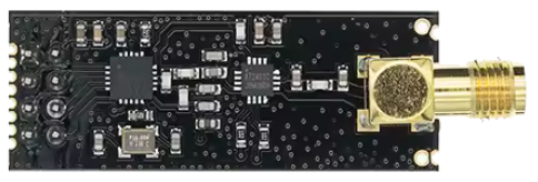
The NRF24 is a low-power, 2.4 GHz wireless transceiver module designed for short-range communication. Manufactured by NRF24, this module is widely used in applications such as remote controls, wireless sensors, and IoT devices. It supports multiple communication channels and can operate in both star and mesh network topologies, making it a versatile choice for wireless data transmission.

Explore Projects Built with NRF24

Use Cirkit Designer to design, explore, and prototype these projects online. Some projects support real-time simulation. Click "Open Project" to start designing instantly!
Arduino Nano and NRF24L01 Based Wireless Remote Control
Image of P.T.S CAR , REMOTE , ADVANCE , FINAL V1: A project utilizing NRF24 in a practical application
This circuit features an Arduino Nano microcontroller interfaced with an NRF24L01 wireless transceiver module, powered by a 4 x AAA battery mount. Four pushbuttons are connected to the Arduino's digital inputs with pull-up resistors, and they are used to send different wireless commands via the NRF24L01 module when pressed. The Arduino's SPI interface (D11/MOSI, D12/MISO, D13/SCK) is used for communication with the NRF24L01, and digital pins D9 and D10 are used for the module's CE and CSN pins, respectively.
Cirkit Designer LogoOpen Project in Cirkit Designer
Arduino UNO with NRF24L01 Wireless Communication Module
Image of Gesture Control Drone: A project utilizing NRF24 in a practical application
This circuit connects an Arduino UNO with an NRF24L01 wireless transceiver module. The Arduino provides power and SPI communication lines to the NRF24L01, enabling it to send and receive wireless data. The code for the Arduino is set up with empty setup and loop functions, ready for the user to implement the wireless communication logic.
Cirkit Designer LogoOpen Project in Cirkit Designer
Arduino Nano Controlled NRF24L01 Wireless Communication System
Image of creato 3.0 receiver circuit diagram: A project utilizing NRF24 in a practical application
This circuit features an Arduino Nano microcontroller interfaced with an NRF24L01 wireless communication module. The Arduino Nano is configured to control multiple devices through PWM signals on pins D2, D3, D4, and D5, which are connected to four 3-pin male connectors. The NRF24L01 module is connected to the Arduino's SPI interface (MOSI, MISO, SCK) and digital pins D7 and D8 for CE and CSN signals, enabling wireless communication capabilities.
Cirkit Designer LogoOpen Project in Cirkit Designer
Arduino UNO with NRF24L01 Wireless Communication Module
Image of Nrf checker: A project utilizing NRF24 in a practical application
This circuit connects an Arduino UNO with an NRF24L01 wireless transceiver module. The Arduino provides power and SPI communication lines to the NRF24L01, enabling wireless data transmission. The code for the Arduino is currently a template with empty setup and loop functions, indicating that the specific functionality for the wireless communication has yet to be implemented.
Cirkit Designer LogoOpen Project in Cirkit Designer

Explore Projects Built with NRF24

Use Cirkit Designer to design, explore, and prototype these projects online. Some projects support real-time simulation. Click "Open Project" to start designing instantly!
Image of P.T.S CAR , REMOTE , ADVANCE , FINAL V1: A project utilizing NRF24 in a practical application
Arduino Nano and NRF24L01 Based Wireless Remote Control
This circuit features an Arduino Nano microcontroller interfaced with an NRF24L01 wireless transceiver module, powered by a 4 x AAA battery mount. Four pushbuttons are connected to the Arduino's digital inputs with pull-up resistors, and they are used to send different wireless commands via the NRF24L01 module when pressed. The Arduino's SPI interface (D11/MOSI, D12/MISO, D13/SCK) is used for communication with the NRF24L01, and digital pins D9 and D10 are used for the module's CE and CSN pins, respectively.
Cirkit Designer LogoOpen Project in Cirkit Designer
Image of Gesture Control Drone: A project utilizing NRF24 in a practical application
Arduino UNO with NRF24L01 Wireless Communication Module
This circuit connects an Arduino UNO with an NRF24L01 wireless transceiver module. The Arduino provides power and SPI communication lines to the NRF24L01, enabling it to send and receive wireless data. The code for the Arduino is set up with empty setup and loop functions, ready for the user to implement the wireless communication logic.
Cirkit Designer LogoOpen Project in Cirkit Designer
Image of creato 3.0 receiver circuit diagram: A project utilizing NRF24 in a practical application
Arduino Nano Controlled NRF24L01 Wireless Communication System
This circuit features an Arduino Nano microcontroller interfaced with an NRF24L01 wireless communication module. The Arduino Nano is configured to control multiple devices through PWM signals on pins D2, D3, D4, and D5, which are connected to four 3-pin male connectors. The NRF24L01 module is connected to the Arduino's SPI interface (MOSI, MISO, SCK) and digital pins D7 and D8 for CE and CSN signals, enabling wireless communication capabilities.
Cirkit Designer LogoOpen Project in Cirkit Designer
Image of Nrf checker: A project utilizing NRF24 in a practical application
Arduino UNO with NRF24L01 Wireless Communication Module
This circuit connects an Arduino UNO with an NRF24L01 wireless transceiver module. The Arduino provides power and SPI communication lines to the NRF24L01, enabling wireless data transmission. The code for the Arduino is currently a template with empty setup and loop functions, indicating that the specific functionality for the wireless communication has yet to be implemented.
Cirkit Designer LogoOpen Project in Cirkit Designer

Common Applications

  • Remote controls for consumer electronics
  • Wireless sensor networks
  • Internet of Things (IoT) devices
  • Home automation systems
  • Industrial monitoring and control systems
  • Wireless data logging

Technical Specifications

The NRF24 module is designed to provide reliable and efficient wireless communication. Below are its key technical specifications:

Parameter Value
Operating Frequency 2.4 GHz ISM band
Data Rate 250 kbps, 1 Mbps, 2 Mbps
Operating Voltage 1.9V to 3.6V
Current Consumption 11.3 mA (transmit at 0 dBm)
Sleep Mode Current 900 nA
Communication Range Up to 100 meters (line of sight)
Modulation Technique GFSK (Gaussian Frequency Shift Keying)
Number of Channels 125
Maximum Payload Size 32 bytes
Interface SPI (Serial Peripheral Interface)
Operating Temperature -40°C to +85°C

Pin Configuration and Descriptions

The NRF24 module typically has 8 pins. Below is the pinout and description:

Pin Name Description
1 GND Ground connection
2 VCC Power supply (1.9V to 3.6V)
3 CE Chip Enable: Activates the module for transmission or reception
4 CSN Chip Select Not: Used to enable or disable SPI communication
5 SCK Serial Clock: SPI clock signal
6 MOSI Master Out Slave In: SPI data input
7 MISO Master In Slave Out: SPI data output
8 IRQ Interrupt Request: Indicates data received or transmission complete (optional)

Usage Instructions

The NRF24 module is commonly used in wireless communication projects. Below are the steps to use it in a circuit:

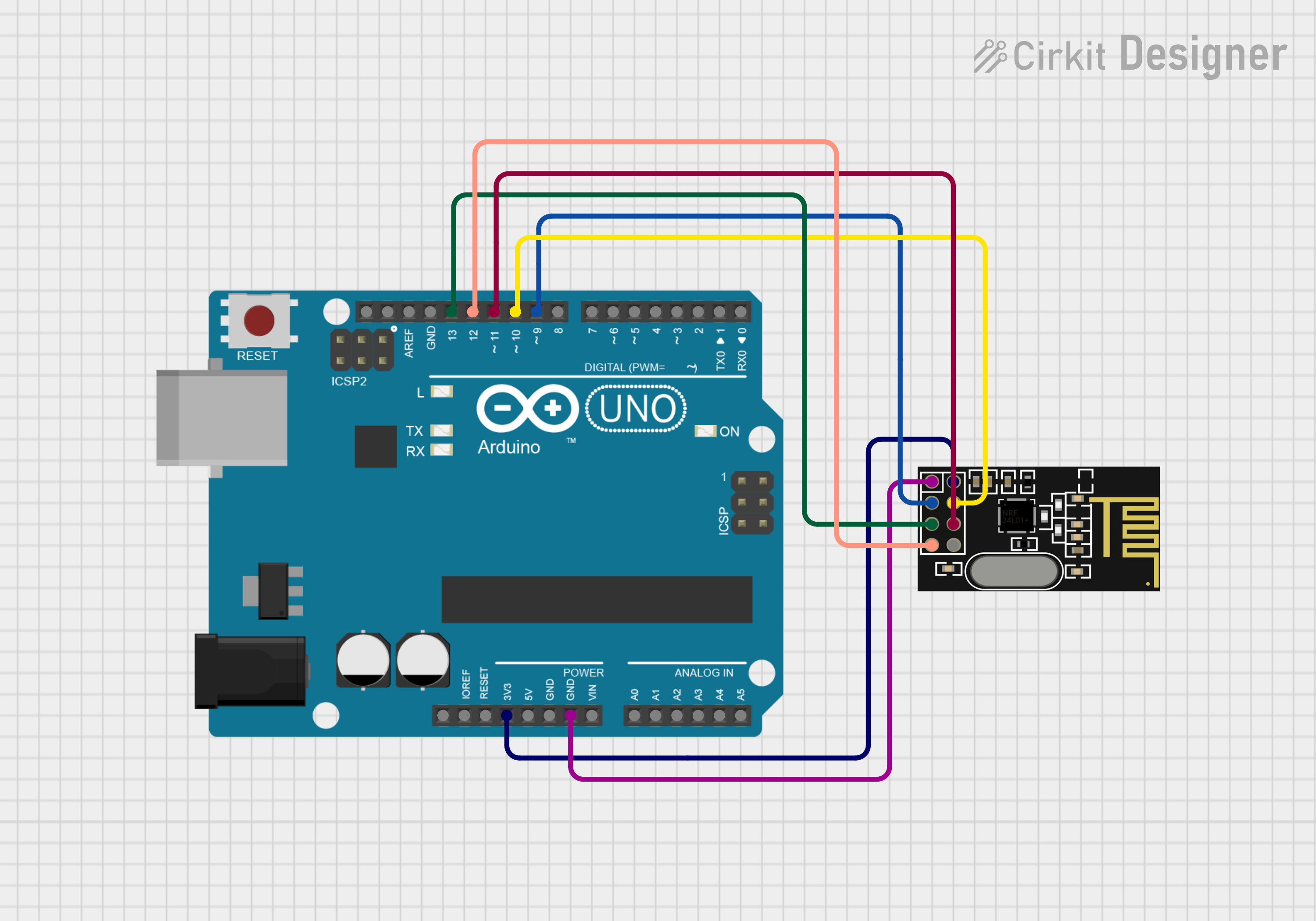
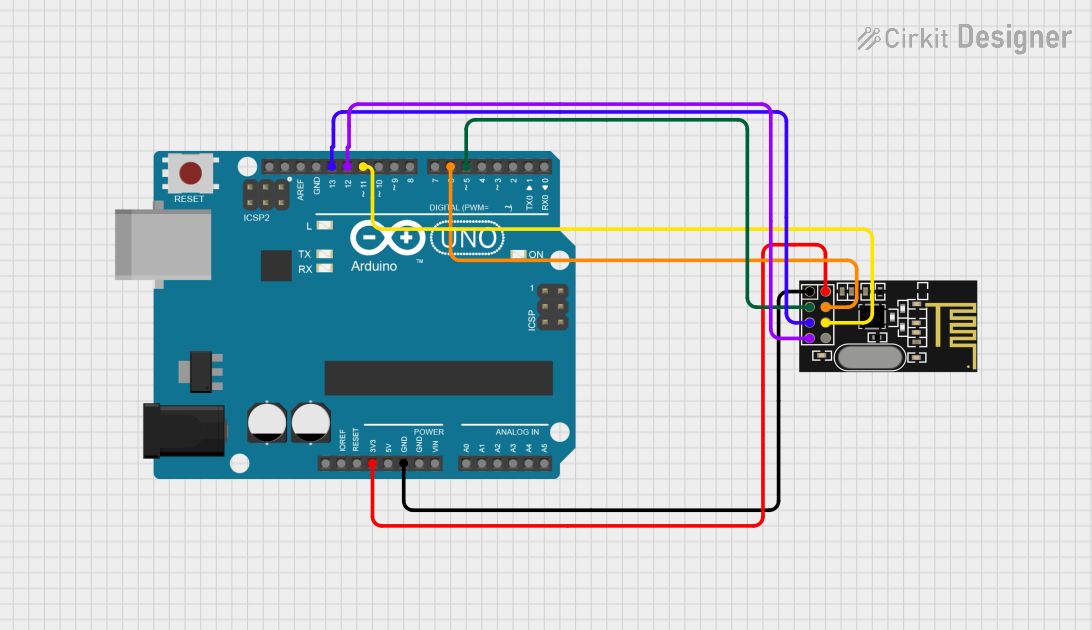
Connecting the NRF24 to an Arduino UNO

  1. Power Supply: Connect the VCC pin to the 3.3V pin on the Arduino UNO. Do not connect it to 5V, as the module is not 5V tolerant.
  2. Ground: Connect the GND pin to the GND pin on the Arduino.
  3. SPI Pins:
    • Connect CE to any digital pin (e.g., D9).
    • Connect CSN to any digital pin (e.g., D10).
    • Connect SCK to the Arduino's SCK pin (D13).
    • Connect MOSI to the Arduino's MOSI pin (D11).
    • Connect MISO to the Arduino's MISO pin (D12).
  4. Optional: Connect the IRQ pin to a digital pin if you want to use interrupts.

Example Code for Arduino UNO

Below is an example code to send and receive data using the NRF24 module with the Arduino UNO. This code uses the popular RF24 library.

#include <SPI.h>
#include <nRF24L01.h>
#include <RF24.h>

// Define the CE and CSN pins
#define CE_PIN 9
#define CSN_PIN 10

// Create an RF24 object
RF24 radio(CE_PIN, CSN_PIN);

// Define the address for communication
const byte address[6] = "00001";

void setup() {
  Serial.begin(9600); // Initialize serial communication
  radio.begin();      // Initialize the NRF24 module
  radio.openWritingPipe(address); // Set the address for transmission
  radio.setPALevel(RF24_PA_LOW);  // Set power level to low
  radio.stopListening();          // Set the module to transmit mode
}

void loop() {
  const char text[] = "Hello, World!"; // Data to send
  bool success = radio.write(&text, sizeof(text)); // Send data

  if (success) {
    Serial.println("Data sent successfully!");
  } else {
    Serial.println("Data transmission failed.");
  }

  delay(1000); // Wait for 1 second before sending again
}

Important Considerations

  • Power Supply: Ensure the module is powered with 3.3V. Using 5V can damage the module.
  • Capacitor: Place a 10 µF capacitor between VCC and GND to stabilize the power supply.
  • Antenna Placement: For optimal range, ensure the antenna is not obstructed by metal objects.
  • SPI Configuration: Ensure the SPI pins on the microcontroller are correctly configured.

Troubleshooting and FAQs

Common Issues and Solutions

  1. No Communication Between Modules:

    • Ensure both modules are set to the same frequency and address.
    • Verify the wiring and connections.
    • Check the power supply voltage (must be 3.3V).
  2. Short Communication Range:

    • Ensure there are no obstructions between the modules.
    • Use an external antenna if available.
    • Check for interference from other 2.4 GHz devices.
  3. Module Not Responding:

    • Verify the SPI connections and pin assignments in the code.
    • Ensure the CE and CSN pins are correctly connected to the microcontroller.

FAQs

Q: Can the NRF24 module communicate with Bluetooth devices?
A: No, the NRF24 uses the 2.4 GHz ISM band but does not support Bluetooth protocols.

Q: What is the maximum range of the NRF24 module?
A: The range is up to 100 meters in line-of-sight conditions. Obstacles and interference can reduce the range.

Q: Can I use multiple NRF24 modules in a single network?
A: Yes, the NRF24 supports up to 6 data pipes, allowing multiple modules to communicate in a star or mesh topology.

Q: Is the NRF24 compatible with 5V microcontrollers?
A: The module itself is not 5V tolerant. Use a level shifter or voltage divider for safe operation with 5V microcontrollers.