How to Use Adafruit Feather nRF52: Examples, Pinouts, and Specs
Introduction
The Adafruit Feather nRF52 is a versatile and powerful development board that harnesses the capabilities of the Nordic nRF52832 System-on-Chip (SoC). This board is part of the Feather ecosystem - Adafruit's line of development boards designed for portability, ease of use, and flexibility. The nRF52 Feather is particularly notable for its Bluetooth Low Energy (BLE) capabilities, ARM Cortex-M4 processor, and a rich set of peripherals, making it an ideal choice for IoT projects, wearable devices, and low-power wireless applications.
Explore Projects Built with Adafruit Feather nRF52

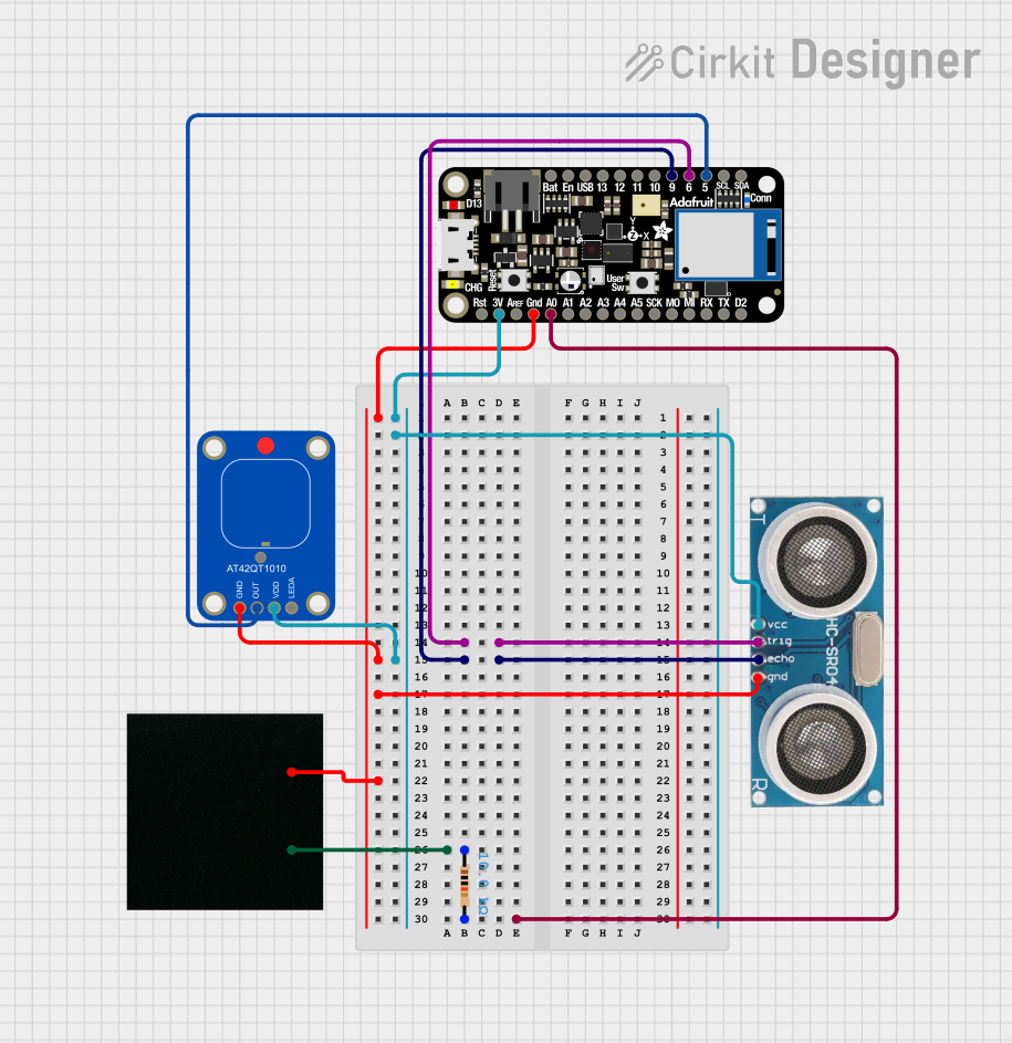

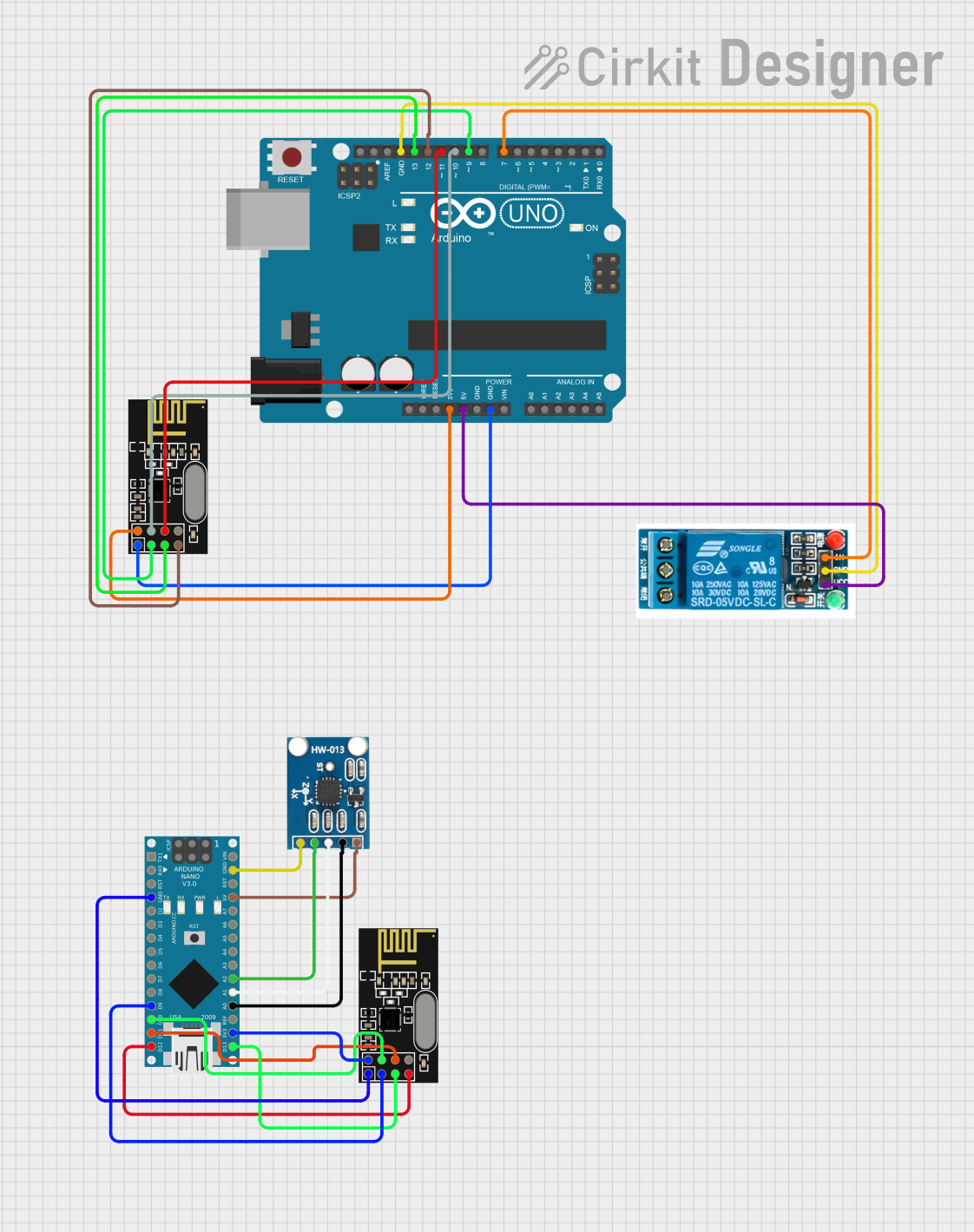
Explore Projects Built with Adafruit Feather nRF52
Common Applications and Use Cases
- Wearable devices and fitness trackers
- Wireless sensor networks
- Home automation systems
- IoT prototypes and products
- BLE-enabled smart gadgets
Technical Specifications
Key Technical Details
- Microcontroller: ARM Cortex-M4 32-bit processor with FPU
- Operating Voltage: 3.3V
- Input Voltage: 3.7-6V via battery, USB, or VIN pin
- I/O Pins: 20 GPIO pins
- Analog Inputs: 6 (12-bit ADC channels)
- PWM Outputs: All GPIOs support PWM
- Clock Speed: 64MHz
- Flash Memory: 512KB
- SRAM: 64KB
- Bluetooth: BLE 4.2/5.0
- Dimensions: 51mm x 23mm x 8mm (without headers)
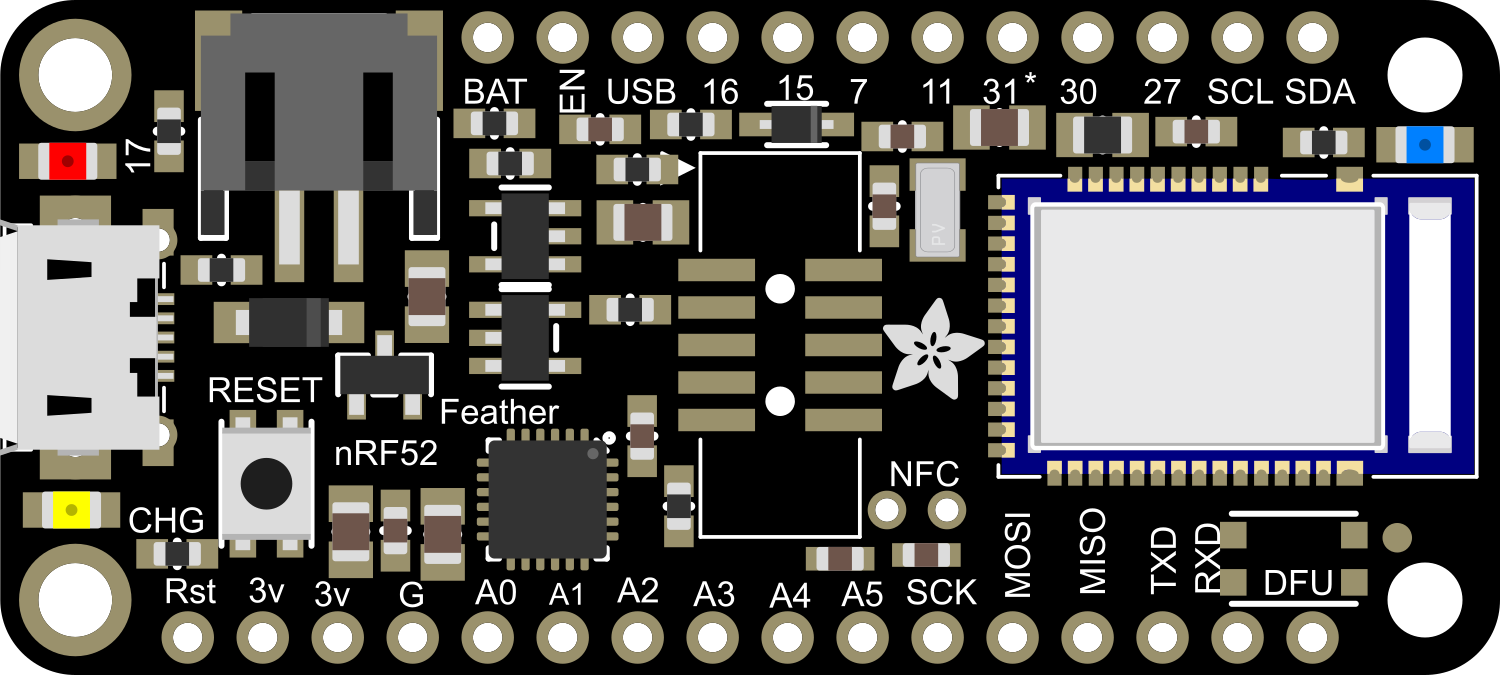
Pin Configuration and Descriptions
| Pin Number | Function | Description |
|---|---|---|
| 1 | GND | Ground |
| 2 | 3V3 | 3.3V output from the regulator |
| 3 | AREF | Analog reference voltage for ADC |
| 4-9 | A0-A5 | Analog input pins |
| 10-17 | D0-D7 | Digital I/O pins |
| 18-19 | SDA, SCL | I2C Data & Clock lines |
| 20 | RX | UART Receive pin |
| 21 | TX | UART Transmit pin |
| 22 | SCK | SPI Clock |
| 23 | MISO | SPI Master In Slave Out |
| 24 | MOSI | SPI Master Out Slave In |
| 25 | #13 | Digital I/O, also used for the onboard LED |
| 26 | RST | Reset pin |
| 27 | USB | USB data lines for programming and power |
Usage Instructions
How to Use the Component in a Circuit
Powering the Board:
- You can power the Adafruit Feather nRF52 via the USB connection, a LiPo battery, or through the VIN pin.
- Ensure that the power source does not exceed the recommended voltage levels to prevent damage.
Programming:
- Install the necessary board support package in your Arduino IDE or preferred development environment.
- Select the Adafruit Feather nRF52 from the list of available boards.
- Connect the board to your computer using a micro USB cable.
- Write your code and upload it to the board using the IDE.
Connecting Peripherals:
- Use the GPIO pins to connect sensors, actuators, and other components.
- Ensure that the connected peripherals are compatible with the board's operating voltage.
Important Considerations and Best Practices
- Always disconnect the board from power sources before making or altering connections.
- Use a current limiting resistor with LEDs and other sensitive components.
- When using BLE functionality, ensure that your code efficiently manages power to optimize battery life.
- Keep the board firmware and libraries up to date to benefit from the latest features and improvements.
Troubleshooting and FAQs
Common Issues Users Might Face
- Board not recognized by the computer:
- Check the USB cable and connections.
- Ensure that the correct drivers are installed.
- Failure to upload code:
- Verify that the correct board and port are selected in the IDE.
- Press the reset button on the board and try uploading again.
- BLE connectivity issues:
- Ensure that the BLE antenna is not obstructed.
- Check the BLE code for proper initialization and error handling.
Solutions and Tips for Troubleshooting
- If the board is not powering up, check the power source and connections.
- For issues with peripherals, verify the wiring and code logic.
- Consult the Adafruit forums and online resources for community support and solutions.
Example Code for Arduino UNO
// Simple Blink example for Adafruit Feather nRF52

void setup() {
  pinMode(LED_BUILTIN, OUTPUT); // Initialize the LED pin as an output
}

void loop() {
  digitalWrite(LED_BUILTIN, HIGH); // Turn the LED on
  delay(1000);                     // Wait for a second
  digitalWrite(LED_BUILTIN, LOW);  // Turn the LED off
  delay(1000);                     // Wait for a second
}
This example code will blink the onboard LED of the Adafruit Feather nRF52. Make sure to select the correct board from the Arduino IDE before uploading the code.
Note: The above code is a simple demonstration. For BLE functionality and advanced features, refer to the Adafruit Feather nRF52 libraries and examples.