How to Use CAN BUS Splitter: Examples, Pinouts, and Specs
Introduction
The CAN BUS Splitter by CubePilot (Manufacturer Part ID: CAN BUS Splitter) is a versatile device designed to divide a single Controller Area Network (CAN) bus signal into multiple outputs. This allows multiple devices to communicate seamlessly on the same CAN bus without interference. It is an essential component for expanding CAN bus networks in applications such as robotics, automotive systems, UAVs, and industrial automation.
Explore Projects Built with CAN BUS Splitter


Explore Projects Built with CAN BUS Splitter
Common Applications and Use Cases
- Unmanned Aerial Vehicles (UAVs): Connecting multiple peripherals like GPS modules, sensors, and controllers to a single CAN bus.
- Automotive Systems: Expanding the CAN bus network for diagnostics, ECUs, and other subsystems.
- Industrial Automation: Integrating multiple sensors and actuators into a single CAN bus network.
- Robotics: Enabling communication between multiple robotic components on a shared CAN bus.
Technical Specifications
The following table outlines the key technical details of the CubePilot CAN BUS Splitter:
| Parameter | Specification |
|---|---|
| Manufacturer | CubePilot |
| Part ID | CAN BUS Splitter |
| Input Voltage Range | 4.5V to 5.5V |
| Maximum Current | 1A (shared across all outputs) |
| Number of Outputs | 4 CAN bus outputs |
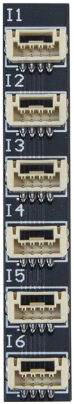
| Connector Type | JST-GH 4-pin connectors |
| Communication Protocol | CAN 2.0 |
| Operating Temperature | -40°C to 85°C |
| Dimensions | 30mm x 20mm x 10mm |
| Weight | 5g |
Pin Configuration and Descriptions
The CAN BUS Splitter uses JST-GH 4-pin connectors for both input and output. The pin configuration is as follows:
| Pin Number | Pin Name | Description |
|---|---|---|
| 1 | VCC | Power supply input (4.5V to 5.5V) |
| 2 | GND | Ground |
| 3 | CAN_H | CAN bus high signal |
| 4 | CAN_L | CAN bus low signal |
Usage Instructions
How to Use the CAN BUS Splitter in a Circuit
Power Supply:
- Connect a regulated 5V power supply to the VCC and GND pins of the input connector.
- Ensure the power supply can provide sufficient current for all connected devices.
CAN Bus Input:
- Connect the CAN_H and CAN_L lines from the main CAN bus to the corresponding pins on the input connector.
CAN Bus Outputs:
- Connect the CAN_H and CAN_L lines of each peripheral device to the corresponding pins on the output connectors.
- Ensure that all devices on the CAN bus have unique IDs to avoid conflicts.
Termination Resistors:
- The CAN bus requires termination resistors (typically 120Ω) at both ends of the bus.
- The CAN BUS Splitter does not include termination resistors, so ensure they are added externally if needed.
Important Considerations and Best Practices
- Cable Length: Keep the cable lengths as short as possible to minimize signal degradation and latency.
- Shielded Cables: Use shielded twisted-pair cables for the CAN_H and CAN_L lines to reduce electromagnetic interference (EMI).
- Device Compatibility: Ensure all connected devices support the CAN 2.0 protocol.
- Power Budget: Verify that the total current consumption of all connected devices does not exceed the 1A limit of the splitter.
Example: Connecting to an Arduino UNO
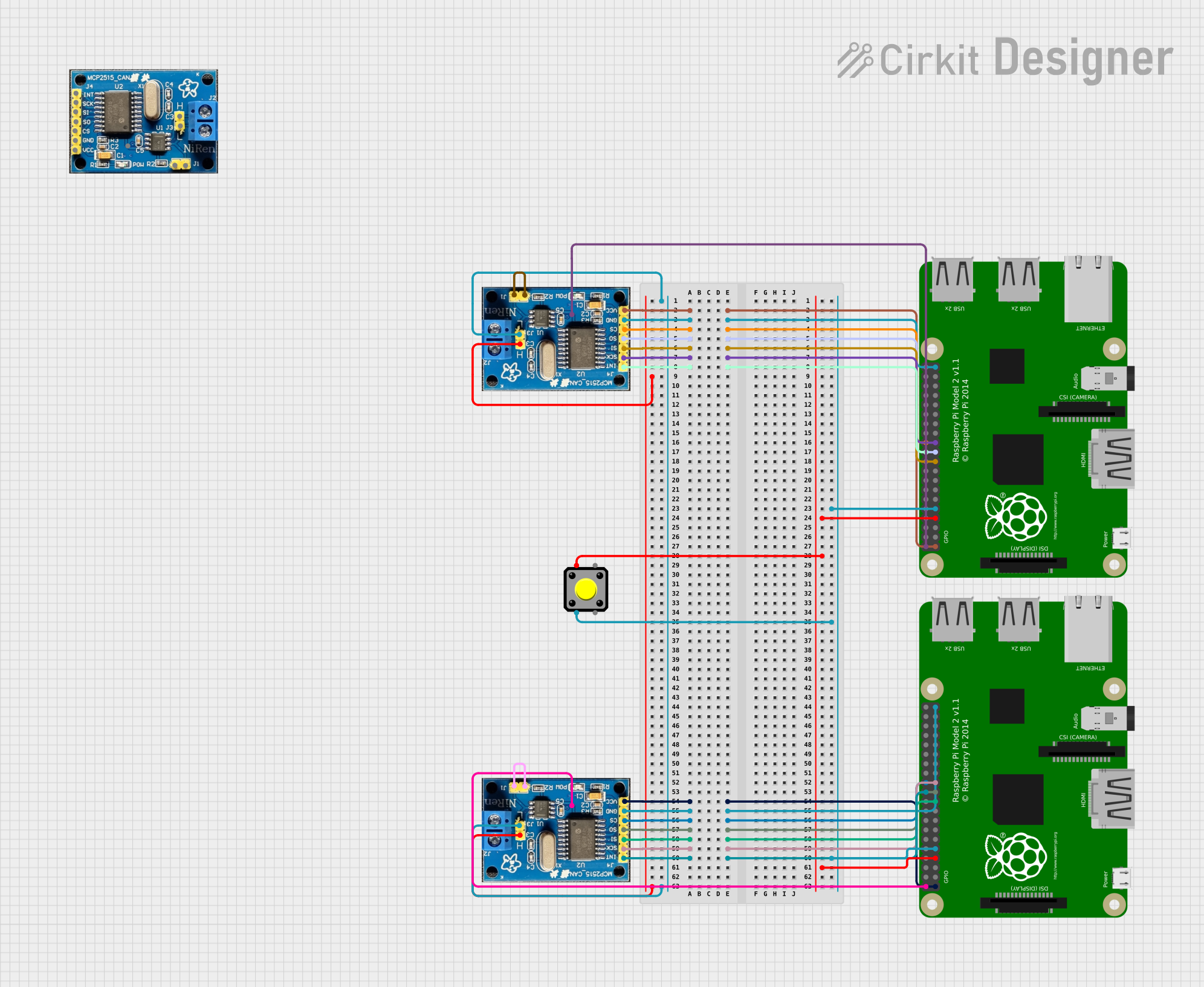
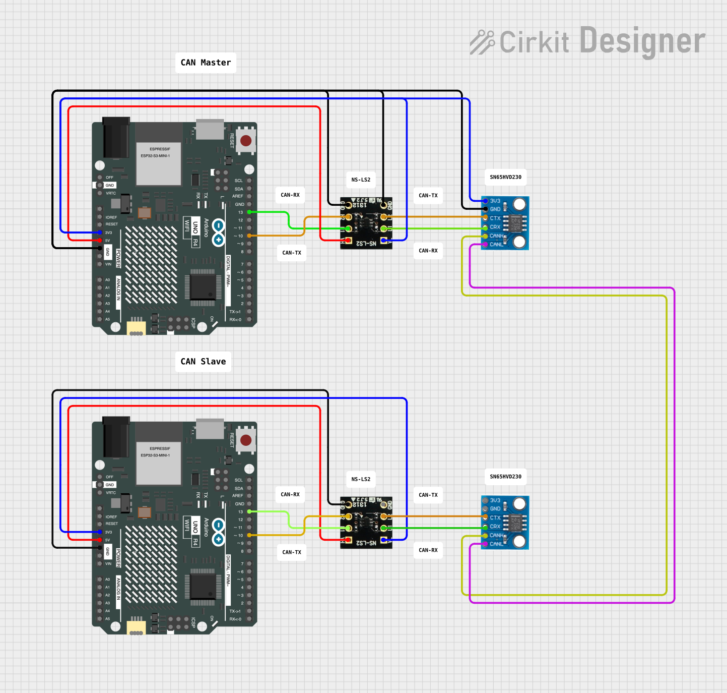
While the CAN BUS Splitter itself does not directly interface with an Arduino UNO, it can be used in conjunction with a CAN transceiver module (e.g., MCP2515). Below is an example Arduino sketch for sending data over the CAN bus:
#include <SPI.h>
#include <mcp2515.h> // Include the MCP2515 CAN library

struct can_frame canMsg; // Define a CAN frame structure
MCP2515 mcp2515(10);     // Initialize MCP2515 with CS pin 10

void setup() {
  Serial.begin(9600);
  // Initialize MCP2515 and set CAN speed to 500 kbps
  if (mcp2515.begin(MCP_ANY, CAN_500KBPS, MCP_8MHZ) == CAN_OK) {
    Serial.println("CAN BUS Initialized Successfully!");
  } else {
    Serial.println("Error Initializing CAN BUS!");
    while (1); // Halt if initialization fails
  }
  mcp2515.setMode(MCP_NORMAL); // Set MCP2515 to normal mode

  // Prepare a CAN message
  canMsg.can_id = 0x100; // Set CAN ID
  canMsg.can_dlc = 2;    // Set data length (2 bytes)
  canMsg.data[0] = 0x55; // First byte of data
  canMsg.data[1] = 0xAA; // Second byte of data
}

void loop() {
  // Send the CAN message
  if (mcp2515.sendMessage(&canMsg) == CAN_OK) {
    Serial.println("Message Sent Successfully!");
  } else {
    Serial.println("Error Sending Message!");
  }
  delay(1000); // Wait 1 second before sending the next message
}
Troubleshooting and FAQs
Common Issues and Solutions
No Communication Between Devices:
- Cause: Missing or incorrect termination resistors.
- Solution: Ensure 120Ω termination resistors are installed at both ends of the CAN bus.
Signal Interference or Noise:
- Cause: Unshielded cables or long cable runs.
- Solution: Use shielded twisted-pair cables and minimize cable lengths.
Power Supply Issues:
- Cause: Insufficient power supply or voltage drop.
- Solution: Use a stable 5V power supply capable of providing sufficient current.
Devices Not Responding:
- Cause: Conflicting CAN IDs or incompatible protocols.
- Solution: Verify that all devices have unique CAN IDs and support the CAN 2.0 protocol.
FAQs
Q: Can I use the CAN BUS Splitter with devices that use different CAN speeds?
A: No, all devices on the CAN bus must operate at the same baud rate for proper communication.
Q: Does the CAN BUS Splitter provide power to connected devices?
A: No, the splitter only distributes the CAN signals. Connected devices must be powered separately.
Q: Can I daisy-chain multiple CAN BUS Splitters?
A: Yes, you can daisy-chain splitters to expand the network, but ensure proper termination and avoid exceeding the maximum bus length.
Q: Is the CAN BUS Splitter compatible with CAN FD?
A: No, the splitter is designed for the CAN 2.0 protocol and does not support CAN FD.