
How to Use Header 5x2: Examples, Pinouts, and Specs
 Design with Header 5x2 in Cirkit Designer
Introduction
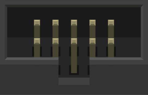
A 5x2 header is a type of connector with 10 pins arranged in two rows of five. It is commonly used in electronic projects for connecting wires, modules, or other circuit boards. These headers are versatile and can be used for both male and female connections, depending on the application. They are often found in microcontroller boards, development kits, and custom PCBs to facilitate easy interfacing and modular design.
Explore Projects Built with Header 5x2
 Open Project in Cirkit Designer
 Open Project in Cirkit Designer
 Open Project in Cirkit Designer
 Open Project in Cirkit Designer
Explore Projects Built with Header 5x2
Open Project in Cirkit DesignerOpen Project in Cirkit DesignerOpen Project in Cirkit DesignerOpen Project in Cirkit DesignerCommon Applications and Use Cases
- Microcontroller Connections: Used to connect peripherals or shields to microcontroller boards like Arduino or Raspberry Pi.
- PCB Interfacing: Provides a reliable way to connect two PCBs together.
- Programming Interfaces: Often used for in-system programming (ISP) or debugging interfaces.
- Prototyping: Ideal for breadboard connections and modular circuit designs.
Technical Specifications
Key Technical Details
- Number of Pins: 10 (arranged in 2 rows of 5)
- Pin Pitch: 2.54 mm (standard spacing)
- Current Rating: Typically 3A per pin (varies by manufacturer)
- Voltage Rating: Up to 250V (varies by manufacturer)
- Material: Gold-plated or tin-plated brass pins with a plastic insulator
- Temperature Range: -40°C to +105°C (varies by manufacturer)
- Mounting Type: Through-hole or surface-mount
Pin Configuration and Descriptions
The 5x2 header does not have a predefined pinout, as it is a generic connector. However, the following table provides an example of how the pins might be used in a typical application, such as an ISP header for microcontroller programming:
| Pin Number | Description | Example Use Case |
|---|---|---|
| 1 | VCC (Power Supply) | Supplies power to the circuit |
| 2 | GND (Ground) | Common ground connection |
| 3 | MOSI (Data Out) | Master Out, Slave In |
| 4 | MISO (Data In) | Master In, Slave Out |
| 5 | SCK (Clock) | Serial Clock |
| 6 | RESET | Resets the microcontroller |
| 7 | NC (Not Connected) | Reserved or unused |
| 8 | NC (Not Connected) | Reserved or unused |
| 9 | NC (Not Connected) | Reserved or unused |
| 10 | NC (Not Connected) | Reserved or unused |
Note: The pinout may vary depending on the specific application or device. Always refer to the datasheet or schematic for your project.
Usage Instructions
How to Use the Component in a Circuit
- Soldering: If using a through-hole 5x2 header, insert the pins into the PCB holes and solder them securely. For surface-mount headers, align the pins with the PCB pads and solder carefully.
- Connecting Wires or Modules: Use compatible connectors, such as female headers or ribbon cables, to connect to the 5x2 header.
- Pin Mapping: Ensure that the pin connections match the intended design. Double-check the pinout to avoid incorrect wiring.
- Programming or Debugging: If using the header for ISP or debugging, connect it to the appropriate programmer or debugger.
Important Considerations and Best Practices
- Pin Alignment: Ensure proper alignment of the header with the mating connector to avoid bent pins or poor connections.
- Current and Voltage Ratings: Do not exceed the specified current and voltage ratings to prevent damage.
- Signal Integrity: For high-speed signals, keep the connections short and use proper grounding to minimize noise.
- Strain Relief: Use strain relief mechanisms, such as cable ties, to prevent stress on the header pins.
Example: Using a 5x2 Header with Arduino UNO
If you are using a 5x2 header to connect an ISP programmer to an Arduino UNO, you can use the following code to enable programming:
// Example code for enabling ISP programming on Arduino UNO
#include <SPI.h>  // Include SPI library for communication

void setup() {
  // Initialize SPI communication
  SPI.begin();

  // Set up pins for ISP communication
  pinMode(10, OUTPUT); // SS (Slave Select) pin
  pinMode(11, OUTPUT); // MOSI (Master Out, Slave In)
  pinMode(12, INPUT);  // MISO (Master In, Slave Out)
  pinMode(13, OUTPUT); // SCK (Serial Clock)

  // Indicate that the setup is complete
  Serial.begin(9600);
  Serial.println("ISP programming ready.");
}

void loop() {
  // Main loop can remain empty for ISP programming
}
Note: Ensure that the ISP programmer is connected to the correct pins on the Arduino UNO.
Troubleshooting and FAQs
Common Issues Users Might Face
- Loose Connections: Poor soldering or misaligned connectors can cause intermittent connections.
- Solution: Re-solder the header or ensure proper alignment with the mating connector.
- Incorrect Pinout: Miswiring the pins can lead to malfunction or damage.
- Solution: Double-check the pinout and wiring before powering the circuit.
- Signal Noise: Long wires or poor grounding can introduce noise in high-speed signals.
- Solution: Use shorter wires and ensure proper grounding.
- Bent Pins: Pins may bend during handling or insertion.
- Solution: Carefully straighten the pins with pliers or replace the header if necessary.
FAQs
Q1: Can I use a 5x2 header for power connections?
A1: Yes, as long as the current and voltage ratings of the header are not exceeded.
Q2: How do I identify pin 1 on a 5x2 header?
A2: Pin 1 is usually marked with a dot, notch, or square pad on the PCB. Refer to the schematic for confirmation.
Q3: Can I use a 5x2 header for high-frequency signals?
A3: Yes, but ensure proper grounding and minimize the length of the connections to reduce noise.
Q4: Are 5x2 headers compatible with ribbon cables?
A4: Yes, they are commonly used with 10-pin ribbon cables for easy connections.
By following this documentation, you can effectively use a 5x2 header in your electronic projects.