Cirkit Designer Logo
Cirkit Designer
Your all-in-one circuit design IDE
Home / 
Component Documentation

How to Use SSR-40 DA: Examples, Pinouts, and Specs

Image of SSR-40 DA
Cirkit Designer LogoDesign with SSR-40 DA in Cirkit Designer

Introduction

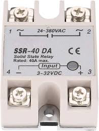
The SSR-40 DA is a Solid State Relay (SSR) manufactured by FQFER, designed for switching AC loads with a maximum current rating of 40A. Unlike traditional electromechanical relays, the SSR-40 DA uses semiconductor devices to achieve fast, silent, and reliable switching without mechanical wear. This makes it ideal for applications requiring high switching frequency and long operational life.

Explore Projects Built with SSR-40 DA

Use Cirkit Designer to design, explore, and prototype these projects online. Some projects support real-time simulation. Click "Open Project" to start designing instantly!
Temperature-Controlled Heating System with SSR and Titanium Resistor
Image of Wire Cut Four Slider 33-2 & 33-3 (Old): A project utilizing SSR-40 DA in a practical application
This circuit is a temperature control system that uses a temperature controller to regulate a heating titanium resistor via a solid-state relay (SSR). The power transformer supplies the necessary voltage to the temperature controller, which in turn controls the SSR to manage the heating element.
Cirkit Designer LogoOpen Project in Cirkit Designer
Multi-Channel Load Cell Measurement System with JYS60 Amplifiers and DAQ Integration
Image of Load Cell Circuit: A project utilizing SSR-40 DA in a practical application
This is a multi-channel load cell measurement system with several JYS60 amplifiers connected to load cells for weight or force sensing. The amplified signals are directed to a DAQ system for data capture, and power is supplied through a barrel jack. Grounding is achieved via an AdaGator Side Black component.
Cirkit Designer LogoOpen Project in Cirkit Designer
Satellite-Based Timing and Navigation System with SDR and Atomic Clock Synchronization
Image of GPS 시스템 측정 구성도_Confirm: A project utilizing SSR-40 DA in a practical application
This circuit appears to be a complex system involving power supply management, GPS and timing synchronization, and data communication. It includes a SI-TEX G1 Satellite Compass for GPS data, an XHTF1021 Atomic Rubidium Clock for precise timing, and Ettus USRP B200 units for software-defined radio communication. Power is supplied through various SMPS units and distributed via terminal blocks and DC jacks. Data communication is facilitated by Beelink MINI S12 N95 computers, RS232 splitters, and a 1000BASE-T Media Converter for network connectivity. RF Directional Couplers are used to interface antennas with the USRP units, and the entire system is likely contained within cases for protection and organization.
Cirkit Designer LogoOpen Project in Cirkit Designer
Battery-Powered ESP32-S3 Controlled Servo System with gForceJoint UART
Image of Copy of Oymotion: A project utilizing SSR-40 DA in a practical application
This circuit is a servo control system powered by a 4 x AAA battery pack, regulated by a step-down DC regulator. An ESP32-S3 microcontroller controls five servos and communicates with a gForceJoint UART sensor, enabling precise servo movements based on sensor inputs.
Cirkit Designer LogoOpen Project in Cirkit Designer

Explore Projects Built with SSR-40 DA

Use Cirkit Designer to design, explore, and prototype these projects online. Some projects support real-time simulation. Click "Open Project" to start designing instantly!
Image of Wire Cut Four Slider 33-2 & 33-3 (Old): A project utilizing SSR-40 DA in a practical application
Temperature-Controlled Heating System with SSR and Titanium Resistor
This circuit is a temperature control system that uses a temperature controller to regulate a heating titanium resistor via a solid-state relay (SSR). The power transformer supplies the necessary voltage to the temperature controller, which in turn controls the SSR to manage the heating element.
Cirkit Designer LogoOpen Project in Cirkit Designer
Image of Load Cell Circuit: A project utilizing SSR-40 DA in a practical application
Multi-Channel Load Cell Measurement System with JYS60 Amplifiers and DAQ Integration
This is a multi-channel load cell measurement system with several JYS60 amplifiers connected to load cells for weight or force sensing. The amplified signals are directed to a DAQ system for data capture, and power is supplied through a barrel jack. Grounding is achieved via an AdaGator Side Black component.
Cirkit Designer LogoOpen Project in Cirkit Designer
Image of GPS 시스템 측정 구성도_Confirm: A project utilizing SSR-40 DA in a practical application
Satellite-Based Timing and Navigation System with SDR and Atomic Clock Synchronization
This circuit appears to be a complex system involving power supply management, GPS and timing synchronization, and data communication. It includes a SI-TEX G1 Satellite Compass for GPS data, an XHTF1021 Atomic Rubidium Clock for precise timing, and Ettus USRP B200 units for software-defined radio communication. Power is supplied through various SMPS units and distributed via terminal blocks and DC jacks. Data communication is facilitated by Beelink MINI S12 N95 computers, RS232 splitters, and a 1000BASE-T Media Converter for network connectivity. RF Directional Couplers are used to interface antennas with the USRP units, and the entire system is likely contained within cases for protection and organization.
Cirkit Designer LogoOpen Project in Cirkit Designer
Image of Copy of Oymotion: A project utilizing SSR-40 DA in a practical application
Battery-Powered ESP32-S3 Controlled Servo System with gForceJoint UART
This circuit is a servo control system powered by a 4 x AAA battery pack, regulated by a step-down DC regulator. An ESP32-S3 microcontroller controls five servos and communicates with a gForceJoint UART sensor, enabling precise servo movements based on sensor inputs.
Cirkit Designer LogoOpen Project in Cirkit Designer

Common Applications and Use Cases

  • Industrial automation systems
  • Heating, ventilation, and air conditioning (HVAC) systems
  • Motor control and industrial machinery
  • Lighting control systems
  • Temperature control in ovens and furnaces
  • Home automation projects

Technical Specifications

The SSR-40 DA is designed to handle high-power AC loads efficiently. Below are its key technical details:

General Specifications

Parameter Value
Manufacturer FQFER
Part ID Relay
Type Solid State Relay (SSR)
Input Control Voltage 3-32V DC
Output Load Voltage 24-380V AC
Maximum Load Current 40A
Trigger Current ≤7.5mA
Isolation Voltage ≥2500V AC
Switching Speed ≤10ms
Operating Temperature -30°C to +75°C
Mounting Type Panel Mount
Weight Approx. 110g

Pin Configuration and Descriptions

The SSR-40 DA has four terminals, as described below:

Pin Number Label Description
1 Input (+) Positive DC control signal input (3-32V DC)
2 Input (-) Negative DC control signal input (ground)
3 Output (L1) AC load terminal (connect to AC live wire)
4 Output (L2) AC load terminal (connect to AC load or neutral)

Usage Instructions

How to Use the SSR-40 DA in a Circuit

  1. Input Side (Control Signal):

    • Connect the positive control signal (3-32V DC) to the Input (+) terminal.
    • Connect the ground of the control signal to the Input (-) terminal.
    • Ensure the control signal voltage is within the specified range to avoid damage.
  2. Output Side (Load Connection):

    • Connect the AC live wire to the Output (L1) terminal.
    • Connect the AC load to the Output (L2) terminal.
    • Ensure the load does not exceed the maximum current rating of 40A.
  3. Mounting:

    • Secure the SSR-40 DA to a heat sink or metal surface using screws to dissipate heat effectively.
    • Use thermal paste between the relay and the heat sink for better thermal conductivity.
  4. Power On:

    • Apply the control signal to the input terminals to activate the relay.
    • The relay will switch the AC load on or off based on the control signal.

Important Considerations and Best Practices

  • Heat Dissipation: The SSR-40 DA generates heat during operation. Always use a heat sink or cooling fan to prevent overheating.
  • Load Protection: Use appropriate fuses or circuit breakers to protect the relay and connected load from overcurrent.
  • Voltage Spikes: For inductive loads (e.g., motors), use a snubber circuit or varistor to suppress voltage spikes and protect the relay.
  • Polarity: Ensure correct polarity when connecting the DC control signal to avoid damage to the relay.

Example: Connecting SSR-40 DA to an Arduino UNO

Below is an example of how to control the SSR-40 DA using an Arduino UNO to switch an AC load:

// Define the pin connected to the SSR control input
const int ssrPin = 7;

void setup() {
  pinMode(ssrPin, OUTPUT); // Set the SSR pin as an output
}

void loop() {
  digitalWrite(ssrPin, HIGH); // Turn on the SSR (AC load ON)
  delay(5000);                // Keep the load ON for 5 seconds
  digitalWrite(ssrPin, LOW);  // Turn off the SSR (AC load OFF)
  delay(5000);                // Keep the load OFF for 5 seconds
}

Note: Ensure the Arduino's ground is connected to the SSR's Input (-) terminal.

Troubleshooting and FAQs

Common Issues and Solutions

  1. Relay Not Switching:

    • Cause: Insufficient control voltage or incorrect polarity.
    • Solution: Verify the control voltage is within the 3-32V DC range and check the polarity.
  2. Overheating:

    • Cause: Inadequate heat dissipation or excessive load current.
    • Solution: Use a heat sink or cooling fan and ensure the load current does not exceed 40A.
  3. Load Not Turning Off:

    • Cause: Inductive load causing voltage spikes.
    • Solution: Add a snubber circuit or varistor across the output terminals.
  4. Flickering Load:

    • Cause: Unstable control signal or loose connections.
    • Solution: Check the control signal source and tighten all connections.

FAQs

Q1: Can the SSR-40 DA switch DC loads?
A1: No, the SSR-40 DA is designed specifically for AC loads. For DC loads, use a DC-specific SSR.

Q2: What is the maximum switching frequency?
A2: The SSR-40 DA can switch loads at a frequency of up to 10ms per cycle, making it suitable for most applications.

Q3: Is electrical isolation provided between the input and output?
A3: Yes, the SSR-40 DA provides electrical isolation with an isolation voltage of ≥2500V AC.

Q4: Can I use the SSR-40 DA without a heat sink?
A4: It is not recommended. Without proper heat dissipation, the relay may overheat and fail.

By following this documentation, users can effectively integrate the SSR-40 DA into their projects and ensure reliable operation.