
How to Use Infineon XMC1100 Boot Kit: Examples, Pinouts, and Specs
 Design with Infineon XMC1100 Boot Kit in Cirkit Designer
Introduction
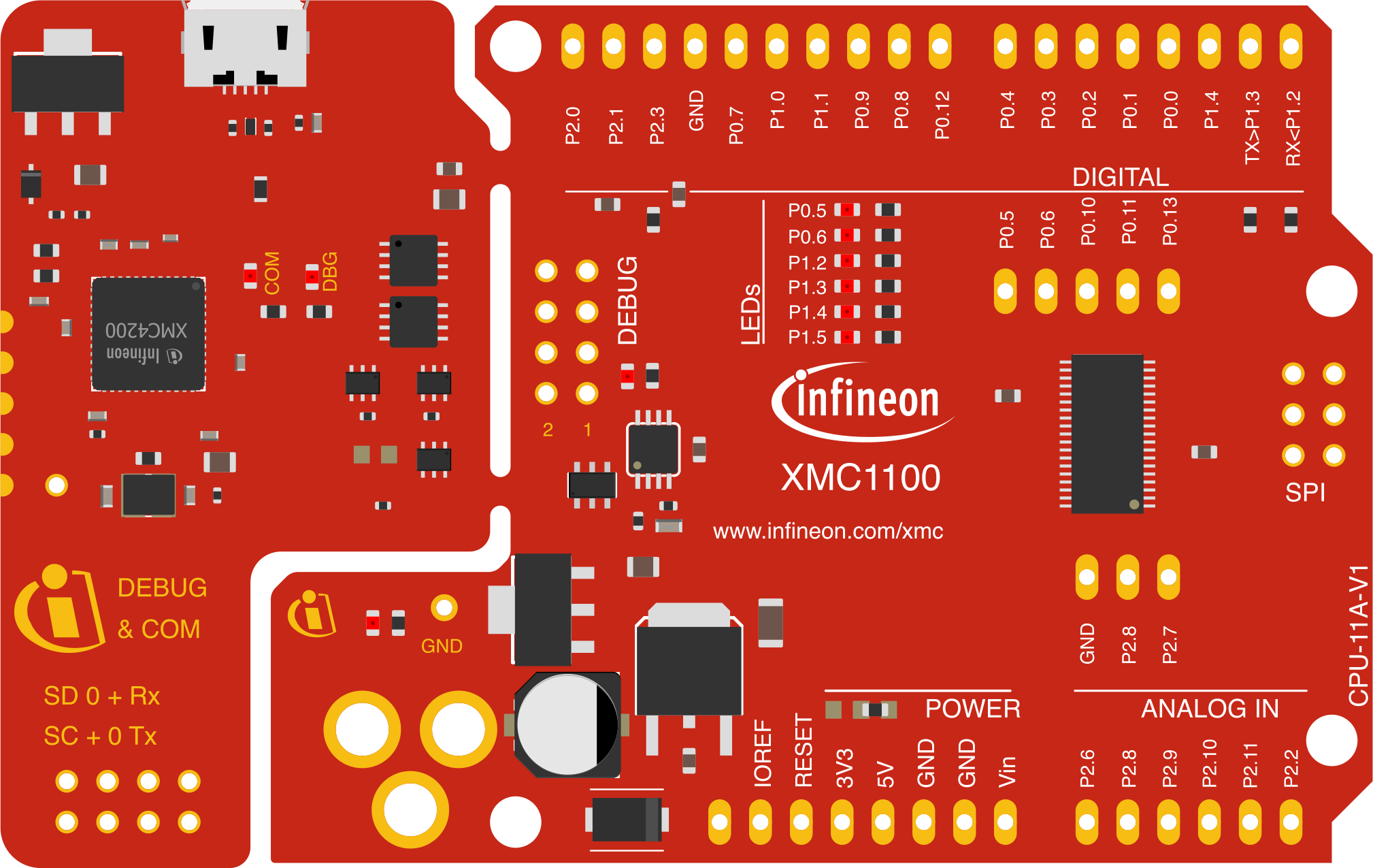
The Infineon XMC1100 Boot Kit (Manufacturer Part ID: KITXMC11BOOT001TOBO1) is a development kit designed for the Infineon XMC1100 microcontroller series. It features a USB interface for programming and debugging, making it an ideal platform for rapid prototyping and testing of embedded applications. The kit is based on the ARM® Cortex®-M0 processor, offering a balance of performance and energy efficiency.
This boot kit is widely used in applications such as:
- Motor control
- Industrial automation
- IoT devices
- Consumer electronics
- General-purpose embedded systems
Explore Projects Built with Infineon XMC1100 Boot Kit
 Open Project in Cirkit Designer
 Open Project in Cirkit Designer
 Open Project in Cirkit Designer
 Open Project in Cirkit Designer
Explore Projects Built with Infineon XMC1100 Boot Kit
Open Project in Cirkit DesignerOpen Project in Cirkit DesignerOpen Project in Cirkit DesignerOpen Project in Cirkit DesignerTechnical Specifications
The following are the key technical details of the Infineon XMC1100 Boot Kit:
General Specifications
| Parameter | Value |
|---|---|
| Microcontroller | XMC1100 (ARM® Cortex®-M0) |
| Operating Voltage | 3.3V |
| Clock Speed | Up to 32 MHz |
| Flash Memory | 64 KB |
| RAM | 16 KB |
| Communication Interfaces | UART, SPI, I2C, CAN |
| Debug Interface | USB (onboard debugger) |
| Power Supply | USB-powered |
| Dimensions | 54 mm x 38 mm |
Pin Configuration and Descriptions
The XMC1100 Boot Kit provides access to the microcontroller's pins via headers. Below is the pin configuration:
Header Pinout
| Pin Number | Pin Name | Functionality | Notes |
|---|---|---|---|
| 1 | VDD | Power Supply (3.3V) | Provides 3.3V to peripherals |
| 2 | GND | Ground | Common ground |
| 3 | P0.0 | GPIO / UART_TXD | Configurable as GPIO or UART |
| 4 | P0.1 | GPIO / UART_RXD | Configurable as GPIO or UART |
| 5 | P0.2 | GPIO / PWM Output | Configurable as GPIO or PWM |
| 6 | P0.3 | GPIO / ADC Input | Configurable as GPIO or ADC |
| 7 | P0.4 | GPIO / SPI_MOSI | Configurable as GPIO or SPI |
| 8 | P0.5 | GPIO / SPI_MISO | Configurable as GPIO or SPI |
| 9 | P0.6 | GPIO / SPI_SCK | Configurable as GPIO or SPI |
| 10 | P0.7 | GPIO / I2C_SCL | Configurable as GPIO or I2C |
| 11 | P0.8 | GPIO / I2C_SDA | Configurable as GPIO or I2C |
| 12 | RESET | Reset Pin | Active low |
Usage Instructions
How to Use the Component in a Circuit
- Powering the Kit: Connect the XMC1100 Boot Kit to your computer using a USB cable. The kit is USB-powered and does not require an external power supply.
- Programming the Microcontroller:
- Install the Infineon DAVE™ IDE (Development Platform for XMC Microcontrollers) from the Infineon website.
- Connect the kit to your computer via USB. The onboard debugger will be detected automatically.
- Write your application code in DAVE™ IDE and upload it to the microcontroller using the integrated debugger.
- Connecting Peripherals:
- Use the pin headers to connect external components such as sensors, actuators, or communication modules.
- Ensure that the voltage levels of connected peripherals are compatible with the 3.3V logic of the XMC1100.
Important Considerations and Best Practices
- Voltage Levels: Ensure that all connected peripherals operate at 3.3V logic levels to avoid damaging the microcontroller.
- Pin Multiplexing: Many pins on the XMC1100 are multiplexed and can serve multiple functions (e.g., GPIO, UART, SPI). Configure the pins appropriately in your code.
- Debugging: Use the onboard debugger for real-time debugging and monitoring of your application.
- Static Protection: Handle the board with care to avoid damage from electrostatic discharge (ESD).
Example Code for Arduino UNO Users
Although the XMC1100 Boot Kit is not directly compatible with Arduino IDE, the following example demonstrates how to configure a GPIO pin as an output using DAVE™ IDE:
#include <DAVE.h> // Include DAVE library for XMC microcontrollers

int main(void) {
    DAVE_STATUS_t status;

    // Initialize DAVE™ library
    status = DAVE_Init();
    if (status != DAVE_STATUS_SUCCESS) {
        // Initialization failed, handle error
        while (1);
    }

    // Configure P0.0 as an output pin
    DIGITAL_IO_SetOutputHigh(&DIGITAL_IO_0); // Turn on the output

    while (1) {
        DIGITAL_IO_ToggleOutput(&DIGITAL_IO_0); // Toggle the output state
        delay(500); // Wait for 500 ms
    }
}
Note: Replace
DIGITAL_IO_0with the appropriate pin configuration in your DAVE™ project.
Troubleshooting and FAQs
Common Issues Users Might Face
Microcontroller Not Detected by IDE:
- Ensure the USB cable is properly connected.
- Verify that the necessary drivers for the onboard debugger are installed.
- Restart the DAVE™ IDE and reconnect the kit.
Program Not Running After Upload:
- Check the power supply and ensure the board is powered on.
- Verify that the correct microcontroller is selected in the IDE.
- Ensure there are no errors in the uploaded code.
Peripheral Not Responding:
- Confirm that the peripheral is connected to the correct pins.
- Verify the pin configuration in your code.
- Check the voltage levels of the peripheral.
Solutions and Tips for Troubleshooting
- Use a multimeter to verify power and signal levels on the pins.
- Refer to the XMC1100 datasheet for detailed information on pin functions and electrical characteristics.
- Consult the Infineon community forums for additional support and resources.
By following this documentation, users can effectively utilize the Infineon XMC1100 Boot Kit for their embedded development projects.