How to Use ESP32-S3-Camera: Examples, Pinouts, and Specs
Introduction
The ESP32-S3-Camera (manufacturer part ID: S3-CAM) is a powerful microcontroller developed by ESP. It features integrated Wi-Fi and Bluetooth capabilities, along with a dedicated camera interface for image capture and processing. This component is designed for IoT applications, smart devices, and projects requiring advanced image processing and wireless communication.
The ESP32-S3-Camera is ideal for applications such as:
- Smart home devices (e.g., security cameras, video doorbells)
- IoT-enabled surveillance systems
- AI-powered image recognition and processing
- Remote monitoring and control systems
- Educational and prototyping projects
Explore Projects Built with ESP32-S3-Camera

Explore Projects Built with ESP32-S3-Camera
Technical Specifications
The ESP32-S3-Camera is built on the ESP32-S3 microcontroller platform, offering high performance and flexibility. Below are the key technical specifications:
General Specifications
| Parameter | Value |
|---|---|
| Microcontroller | ESP32-S3 |
| Wireless Connectivity | Wi-Fi 802.11 b/g/n, Bluetooth 5.0 |
| Camera Interface | 8-bit DVP (Digital Video Port) |
| Flash Memory | Up to 16 MB (external SPI flash) |
| PSRAM | Up to 8 MB (external) |
| Operating Voltage | 3.3V |
| GPIO Pins | 45 (configurable for various peripherals) |
| CPU | Dual-core Xtensa LX7, up to 240 MHz |
| AI Acceleration | Vector instructions for AI/ML workloads |
| Operating Temperature | -40°C to 85°C |
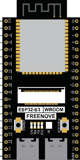
Pin Configuration
The ESP32-S3-Camera module includes a variety of pins for power, communication, and camera interfacing. Below is a summary of the key pin configurations:
Power and Ground Pins
| Pin Name | Description |
|---|---|
| 3V3 | 3.3V power input |
| GND | Ground |
Camera Interface Pins
| Pin Name | Description |
|---|---|
| D0-D7 | Camera data pins (8-bit) |
| VSYNC | Vertical sync signal |
| HREF | Horizontal reference signal |
| PCLK | Pixel clock |
| XCLK | External clock input |
| RESET | Camera reset signal |
Communication Pins
| Pin Name | Description |
|---|---|
| TXD0 | UART0 transmit |
| RXD0 | UART0 receive |
| SCL | I2C clock |
| SDA | I2C data |
| MOSI | SPI master-out, slave-in |
| MISO | SPI master-in, slave-out |
| SCK | SPI clock |
| CS | SPI chip select |
Usage Instructions
The ESP32-S3-Camera can be used in a variety of projects, from simple image capture to advanced AI-based image recognition. Below are the steps to get started:
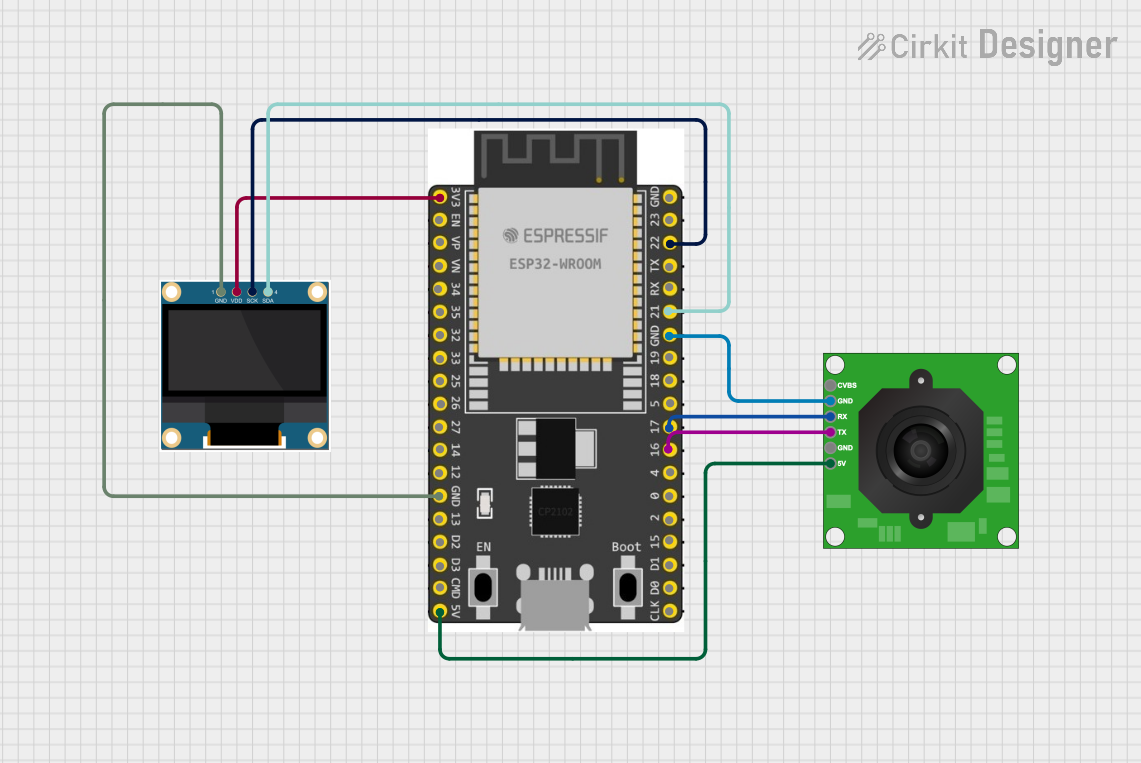
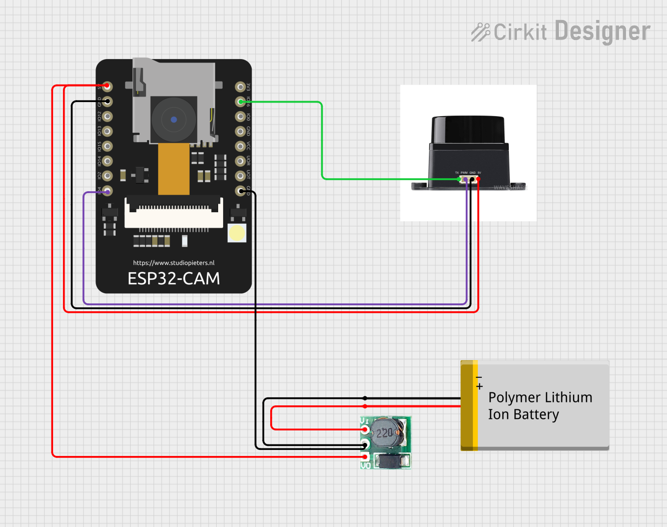
Connecting the ESP32-S3-Camera
- Power the Module: Connect the 3V3 pin to a 3.3V power source and GND to ground.
- Connect the Camera: Attach a compatible camera module (e.g., OV2640) to the camera interface pins (D0-D7, VSYNC, HREF, PCLK, XCLK, RESET).
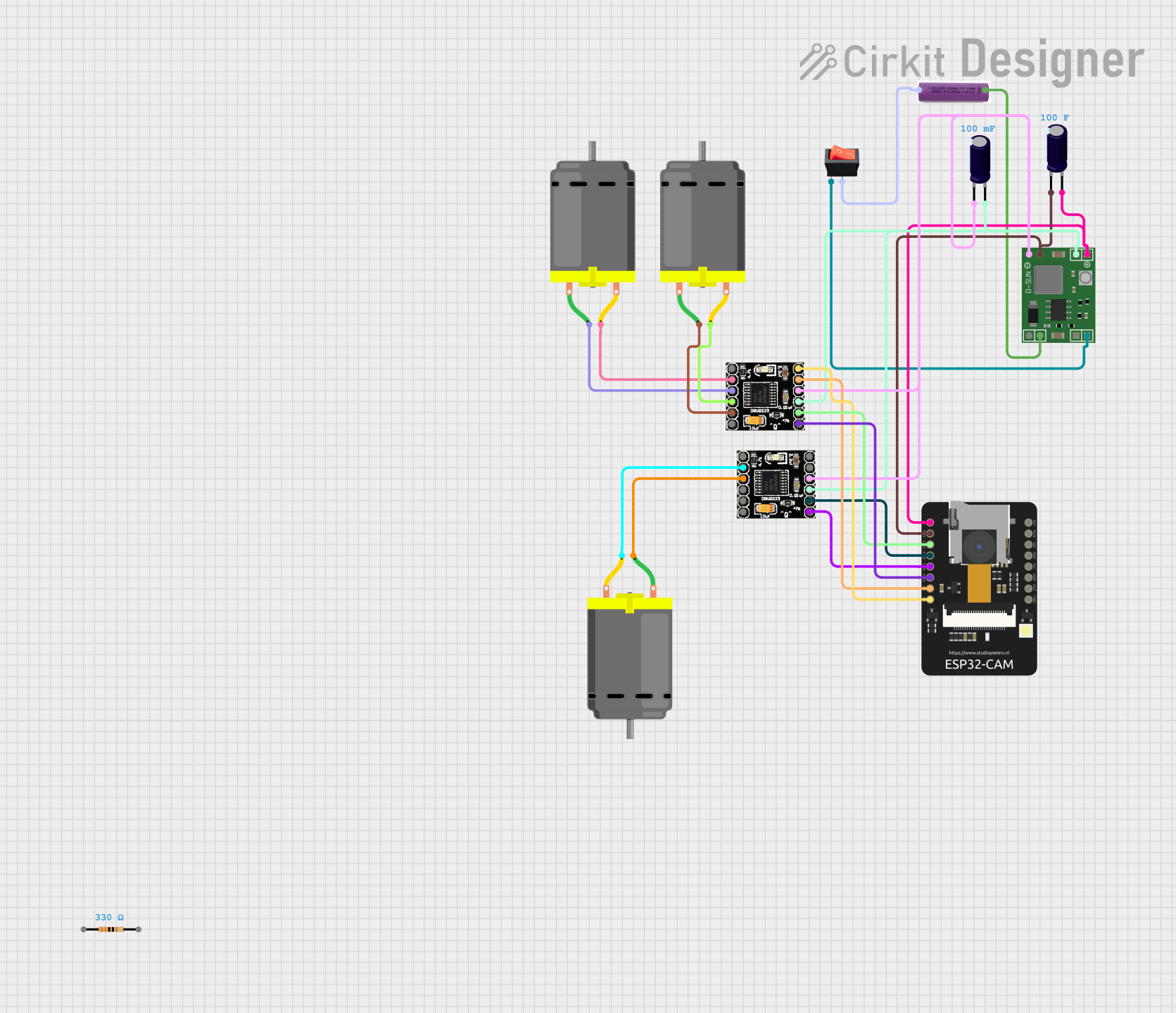
- Set Up Communication: Use UART, I2C, or SPI for communication with other devices or microcontrollers.
- Program the Module: Use the Arduino IDE or ESP-IDF (Espressif IoT Development Framework) to upload your code.
Example Code for Arduino IDE
Below is an example of how to capture an image using the ESP32-S3-Camera and save it to an SD card:
#include "esp_camera.h"
#include "SD_MMC.h"

// Configure the camera pins
#define PWDN_GPIO_NUM    -1 // Power down pin not used
#define RESET_GPIO_NUM   -1 // Reset pin not used
#define XCLK_GPIO_NUM    0  // External clock pin
#define SIOD_GPIO_NUM    26 // I2C data pin
#define SIOC_GPIO_NUM    27 // I2C clock pin
#define Y9_GPIO_NUM      35 // Camera data pins
#define Y8_GPIO_NUM      34
#define Y7_GPIO_NUM      39
#define Y6_GPIO_NUM      36
#define Y5_GPIO_NUM      21
#define Y4_GPIO_NUM      19
#define Y3_GPIO_NUM      18
#define Y2_GPIO_NUM      5
#define VSYNC_GPIO_NUM   25 // Vertical sync pin
#define HREF_GPIO_NUM    23 // Horizontal reference pin
#define PCLK_GPIO_NUM    22 // Pixel clock pin

void setup() {
  Serial.begin(115200);

  // Initialize the camera
  camera_config_t config;
  config.ledc_channel = LEDC_CHANNEL_0;
  config.ledc_timer = LEDC_TIMER_0;
  config.pin_d0 = Y2_GPIO_NUM;
  config.pin_d1 = Y3_GPIO_NUM;
  config.pin_d2 = Y4_GPIO_NUM;
  config.pin_d3 = Y5_GPIO_NUM;
  config.pin_d4 = Y6_GPIO_NUM;
  config.pin_d5 = Y7_GPIO_NUM;
  config.pin_d6 = Y8_GPIO_NUM;
  config.pin_d7 = Y9_GPIO_NUM;
  config.pin_xclk = XCLK_GPIO_NUM;
  config.pin_pclk = PCLK_GPIO_NUM;
  config.pin_vsync = VSYNC_GPIO_NUM;
  config.pin_href = HREF_GPIO_NUM;
  config.pin_sscb_sda = SIOD_GPIO_NUM;
  config.pin_sscb_scl = SIOC_GPIO_NUM;
  config.pin_pwdn = PWDN_GPIO_NUM;
  config.pin_reset = RESET_GPIO_NUM;
  config.xclk_freq_hz = 20000000;
  config.pixel_format = PIXFORMAT_JPEG;

  if (esp_camera_init(&config) != ESP_OK) {
    Serial.println("Camera init failed");
    return;
  }

  // Initialize SD card
  if (!SD_MMC.begin()) {
    Serial.println("SD Card Mount Failed");
    return;
  }

  // Capture an image
  camera_fb_t *fb = esp_camera_fb_get();
  if (!fb) {
    Serial.println("Camera capture failed");
    return;
  }

  // Save the image to the SD card
  File file = SD_MMC.open("/image.jpg", FILE_WRITE);
  if (!file) {
    Serial.println("Failed to open file for writing");
    return;
  }
  file.write(fb->buf, fb->len);
  file.close();
  esp_camera_fb_return(fb);

  Serial.println("Image saved to SD card");
}

void loop() {
  // Nothing to do here
}
Best Practices
- Use a stable 3.3V power supply to avoid damage to the module.
- Ensure proper grounding to prevent noise in the camera signals.
- Use heat sinks or cooling if the module operates in high-temperature environments.
- When using Wi-Fi, ensure the antenna is not obstructed for optimal signal strength.
Troubleshooting and FAQs
Common Issues
Camera Initialization Fails
- Ensure the camera is properly connected to the interface pins.
- Verify the camera module is compatible with the ESP32-S3-Camera.
Image Capture Fails
- Check the power supply voltage (must be 3.3V).
- Ensure the SD card is properly formatted and inserted.
Wi-Fi or Bluetooth Connectivity Issues
- Verify the antenna is connected and unobstructed.
- Check the Wi-Fi credentials in your code.
FAQs
Q: Can I use a different camera module?
A: Yes, as long as the camera module supports an 8-bit DVP interface and is compatible with the ESP32-S3.
Q: What is the maximum resolution supported?
A: The maximum resolution depends on the camera module used. For example, the OV2640 supports up to 1600x1200 (UXGA).
Q: Can I use this module with an Arduino UNO?
A: No, the ESP32-S3-Camera is a standalone microcontroller and does not require an Arduino UNO. However, it can communicate with other microcontrollers via UART, I2C, or SPI.
Q: How do I update the firmware?
A: Use the ESP-IDF or Arduino IDE to upload new firmware via the USB interface or OTA (Over-the-Air) updates.