How to Use Raspberry Pi Zero 2W: Examples, Pinouts, and Specs
Introduction
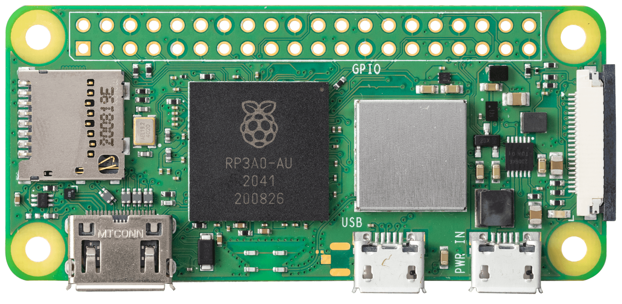
The Raspberry Pi Zero 2W, manufactured by Raspberry Pi, is a compact, low-cost single-board computer designed for DIY projects, embedded applications, and educational purposes. It features a quad-core processor, wireless connectivity, and GPIO pins for interfacing with various electronic components. Despite its small size, the Raspberry Pi Zero 2W delivers impressive performance and versatility, making it a popular choice for hobbyists, developers, and educators.
Explore Projects Built with Raspberry Pi Zero 2W
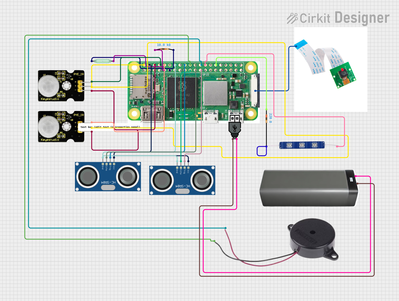
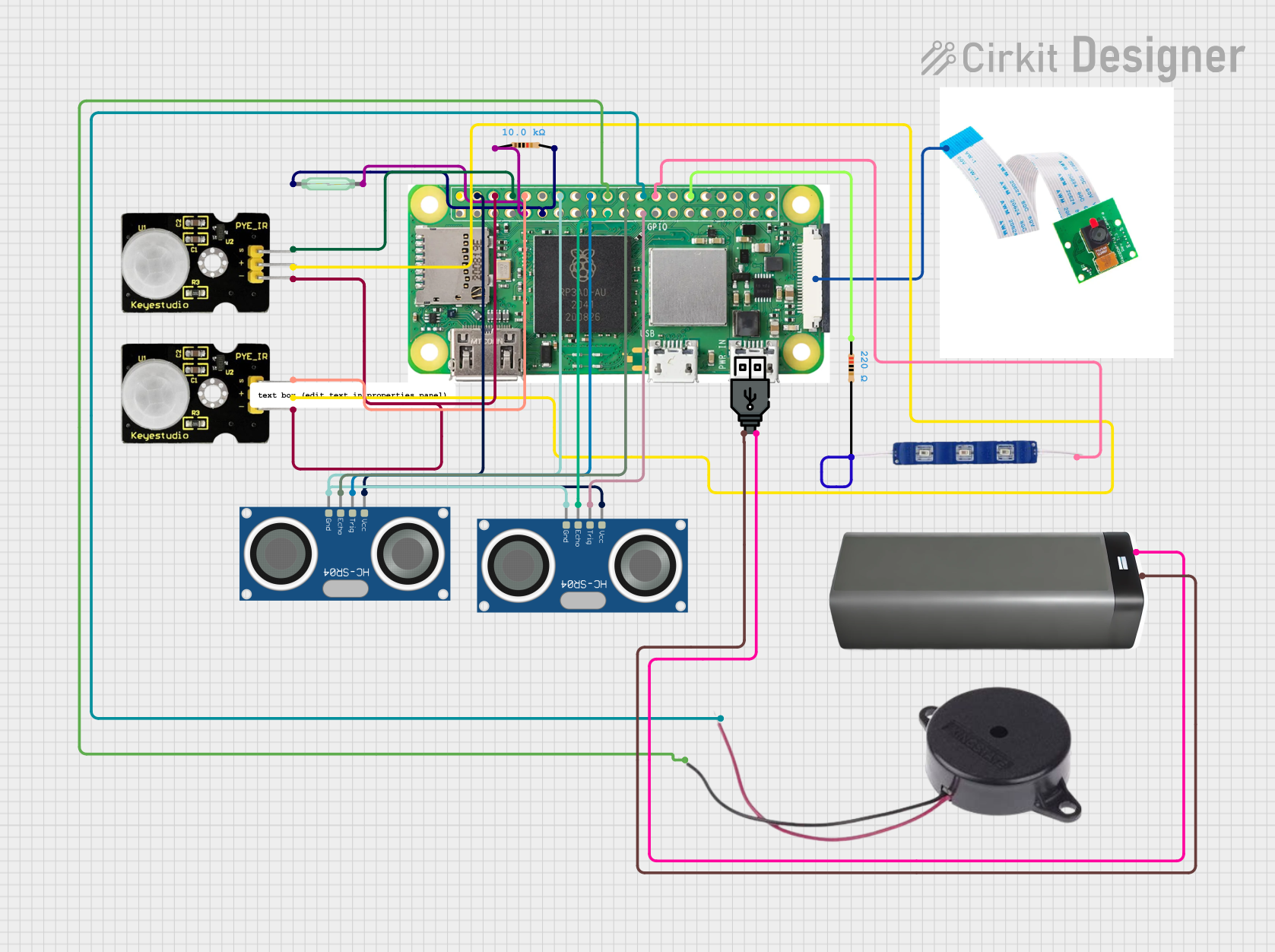
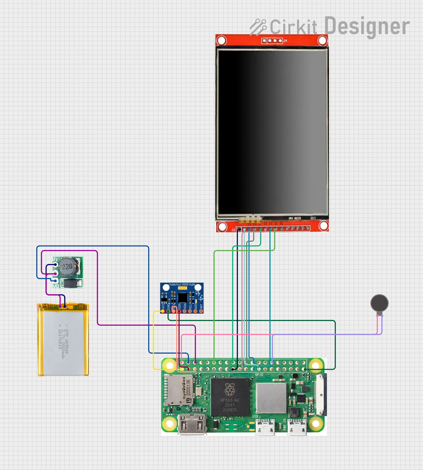

Explore Projects Built with Raspberry Pi Zero 2W
Common Applications and Use Cases
- IoT (Internet of Things) devices and smart home automation
- Robotics and embedded systems
- Media streaming and playback
- Retro gaming consoles
- Prototyping and educational projects
- Low-power computing applications
Technical Specifications
Key Technical Details
| Specification | Details |
|---|---|
| Processor | Broadcom BCM2710A1, quad-core Cortex-A53 |
| Clock Speed | 1 GHz |
| RAM | 512 MB LPDDR2 |
| Wireless Connectivity | 802.11 b/g/n Wi-Fi, Bluetooth 4.2, BLE |
| GPIO Pins | 40-pin header (unpopulated) |
| Video Output | Mini HDMI (1080p at 30fps) |
| USB Ports | 1x Micro USB (data), 1x Micro USB (power) |
| Storage | MicroSD card slot |
| Power Supply | 5V/2.5A via Micro USB |
| Dimensions | 65mm x 30mm x 5mm |
| Weight | 9g |
Pin Configuration and Descriptions
The Raspberry Pi Zero 2W features a 40-pin GPIO header (unpopulated by default). Below is the pinout for the GPIO header:
| Pin Number | Pin Name | Functionality |
|---|---|---|
| 1 | 3.3V | Power (3.3V) |
| 2 | 5V | Power (5V) |
| 3 | GPIO2 (SDA1) | I2C Data Line |
| 4 | 5V | Power (5V) |
| 5 | GPIO3 (SCL1) | I2C Clock Line |
| 6 | GND | Ground |
| 7 | GPIO4 | General Purpose I/O |
| 8 | GPIO14 (TXD) | UART Transmit |
| 9 | GND | Ground |
| 10 | GPIO15 (RXD) | UART Receive |
| ... | ... | ... (Refer to official documentation for full pinout) |
Usage Instructions
How to Use the Raspberry Pi Zero 2W in a Circuit
- Powering the Board: Use a 5V/2.5A power supply connected to the Micro USB power port.
- Connecting Peripherals: Attach a mini HDMI cable for video output, a USB OTG adapter for peripherals like a keyboard or mouse, and a microSD card with the Raspberry Pi OS installed.
- GPIO Interfacing: Solder a 40-pin header to the GPIO pads if needed. Use jumper wires to connect the GPIO pins to external components like LEDs, sensors, or motors.
- Wireless Connectivity: Configure Wi-Fi and Bluetooth through the Raspberry Pi OS for remote access and communication.
Important Considerations and Best Practices
- Heat Management: Although the Raspberry Pi Zero 2W is energy-efficient, consider using a heatsink for prolonged high-performance tasks.
- Power Supply: Ensure a stable 5V/2.5A power source to avoid performance issues or unexpected shutdowns.
- Static Precautions: Handle the board with care to avoid damage from electrostatic discharge (ESD).
- Software Updates: Regularly update the Raspberry Pi OS to ensure compatibility and security.
Example: Blinking an LED with GPIO and Python
Below is an example of how to blink an LED connected to GPIO17 (pin 11) using Python:
Import the GPIO and time libraries
import RPi.GPIO as GPIO import time
Set up GPIO mode and pin
GPIO.setmode(GPIO.BCM) # Use Broadcom pin numbering GPIO.setup(17, GPIO.OUT) # Set GPIO17 as an output pin
try: while True: GPIO.output(17, GPIO.HIGH) # Turn LED on time.sleep(1) # Wait for 1 second GPIO.output(17, GPIO.LOW) # Turn LED off time.sleep(1) # Wait for 1 second except KeyboardInterrupt: # Clean up GPIO settings on exit GPIO.cleanup()
Connecting to an Arduino UNO
The Raspberry Pi Zero 2W can communicate with an Arduino UNO via UART, I2C, or SPI. For example, to send data via UART:
- Connect the Raspberry Pi's GPIO14 (TXD) to the Arduino's RX pin.
- Connect the Raspberry Pi's GPIO15 (RXD) to the Arduino's TX pin.
- Use a common ground between the two devices.
Troubleshooting and FAQs
Common Issues and Solutions
No Power or Boot Failure:
- Ensure the power supply provides 5V/2.5A.
- Check the microSD card for proper installation and a valid Raspberry Pi OS image.
Wi-Fi Not Connecting:
- Verify the Wi-Fi credentials in the Raspberry Pi OS settings.
- Ensure the router is within range and supports 2.4 GHz Wi-Fi.
GPIO Pins Not Working:
- Confirm the correct GPIO pin numbering (BCM vs. physical pin numbers).
- Check for proper connections and ensure the pins are not damaged.
Overheating:
- Use a heatsink or active cooling if the board is running intensive tasks for extended periods.
FAQs
Q: Can I power the Raspberry Pi Zero 2W via GPIO pins?
A: Yes, you can power the board by supplying 5V to the 5V GPIO pin and connecting GND to a ground pin. However, this bypasses the onboard power protection circuitry, so proceed with caution.
Q: What operating systems are compatible with the Raspberry Pi Zero 2W?
A: The Raspberry Pi Zero 2W supports Raspberry Pi OS, as well as other Linux-based distributions like Ubuntu and specialized OSes for IoT and media applications.
Q: Can I use the Raspberry Pi Zero 2W for AI/ML projects?
A: While the Raspberry Pi Zero 2W is not as powerful as other Raspberry Pi models, it can handle lightweight AI/ML tasks using frameworks like TensorFlow Lite.
Q: How do I enable SSH for headless setup?
A: Place an empty file named ssh (without any extension) in the boot partition of the microSD card before inserting it into the Raspberry Pi. This will enable SSH on boot.
By following this documentation, users can effectively utilize the Raspberry Pi Zero 2W for a wide range of projects and applications.