How to Use ESP32 38pin Narrow: Examples, Pinouts, and Specs
Introduction
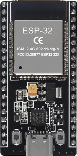
The ESP32 38pin Narrow, manufactured by NodeMCU, is a compact and powerful microcontroller designed for Internet of Things (IoT) applications. It features integrated Wi-Fi and Bluetooth capabilities, making it an excellent choice for wireless communication projects. With 38 pins, this module offers versatile connectivity and a wide range of input/output (I/O) options, enabling developers to create complex and feature-rich systems.
Explore Projects Built with ESP32 38pin Narrow


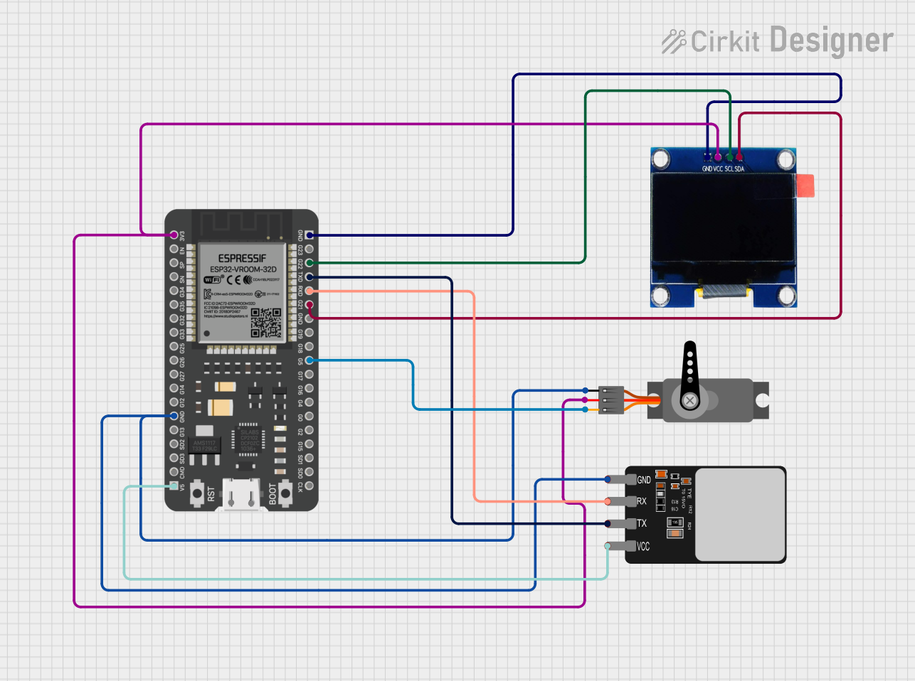
Explore Projects Built with ESP32 38pin Narrow
Common Applications and Use Cases
- IoT devices and smart home automation
- Wireless sensor networks
- Wearable technology
- Robotics and automation systems
- Data logging and remote monitoring
- Prototyping and educational projects
Technical Specifications
The ESP32 38pin Narrow is built on the ESP32 dual-core processor, which provides high performance and low power consumption. Below are the key technical details:
General Specifications
| Parameter | Value |
|---|---|
| Microcontroller | ESP32-D0WDQ6 |
| Architecture | 32-bit Xtensa LX6 dual-core |
| Clock Speed | Up to 240 MHz |
| Flash Memory | 4 MB (external) |
| SRAM | 520 KB |
| Wi-Fi | 802.11 b/g/n |
| Bluetooth | v4.2 BR/EDR and BLE |
| Operating Voltage | 3.3V |
| Input Voltage (VIN) | 5V (via USB or VIN pin) |
| GPIO Pins | 30 |
| ADC Channels | 18 |
| DAC Channels | 2 |
| Communication Interfaces | UART, SPI, I2C, I2S, CAN, PWM |
| Power Consumption | Ultra-low power modes available |
Pin Configuration and Descriptions
The ESP32 38pin Narrow has 38 pins, each with specific functions. Below is a summary of the pin configuration:
| Pin Number | Pin Name | Function Description |
|---|---|---|
| 1 | EN | Enable pin. Active high to enable the module. |
| 2 | IO0 | GPIO0, used for boot mode selection. |
| 3 | IO1 (TX0) | GPIO1, UART0 TX (serial communication). |
| 4 | IO3 (RX0) | GPIO3, UART0 RX (serial communication). |
| 5 | IO4 | GPIO4, general-purpose I/O. |
| 6 | IO5 | GPIO5, general-purpose I/O. |
| 7 | VIN | Input voltage (5V). |
| 8 | GND | Ground. |
| ... | ... | ... (Refer to the full datasheet for details). |
Note: Some pins have multiple functions (e.g., ADC, PWM, I2C). Refer to the ESP32 datasheet for advanced configurations.
Usage Instructions
How to Use the ESP32 38pin Narrow in a Circuit
Powering the Module:
- Connect the VIN pin to a 5V power source or use the micro-USB port for power and programming.
- Ensure the GND pin is connected to the ground of your circuit.
Programming the ESP32:
- Use the Arduino IDE or ESP-IDF (Espressif IoT Development Framework) for programming.
- Install the ESP32 board package in the Arduino IDE via the Board Manager.
- Connect the ESP32 to your computer using a USB cable.
Connecting Peripherals:
- Use the GPIO pins for digital I/O, ADC pins for analog input, and DAC pins for analog output.
- For communication, use UART, SPI, or I2C interfaces as needed.
Example: Blinking an LED with Arduino IDE
The following code demonstrates how to blink an LED connected to GPIO2:
// Define the GPIO pin where the LED is connected
#define LED_PIN 2

void setup() {
  pinMode(LED_PIN, OUTPUT); // Set the LED pin as an output
}

void loop() {
  digitalWrite(LED_PIN, HIGH); // Turn the LED on
  delay(1000);                // Wait for 1 second
  digitalWrite(LED_PIN, LOW);  // Turn the LED off
  delay(1000);                // Wait for 1 second
}
Important Considerations and Best Practices
- Voltage Levels: The ESP32 operates at 3.3V logic levels. Avoid applying 5V directly to GPIO pins.
- Boot Mode: Ensure GPIO0 is pulled low during boot to enter programming mode.
- Power Supply: Use a stable power source to avoid unexpected resets or malfunctions.
- Wi-Fi Interference: Place the module away from metal objects or other sources of interference for optimal Wi-Fi performance.
Troubleshooting and FAQs
Common Issues and Solutions
ESP32 Not Detected by Computer:
- Ensure the correct USB driver (e.g., CP210x or CH340) is installed.
- Check the USB cable for damage or try a different cable.
Upload Fails with "Failed to Connect" Error:
- Hold the "BOOT" button on the ESP32 while uploading the code.
- Verify that GPIO0 is pulled low during programming.
Wi-Fi Connection Issues:
- Double-check the SSID and password in your code.
- Ensure the router is within range and supports 2.4 GHz Wi-Fi.
Random Resets or Instability:
- Use a capacitor (e.g., 10 µF) across the power supply pins to stabilize voltage.
- Avoid overloading the GPIO pins with high-current devices.
FAQs
Q: Can I use the ESP32 38pin Narrow with a 5V sensor?
A: Yes, but you will need a level shifter to convert the 5V signal to 3.3V for the ESP32.
Q: How do I enable deep sleep mode?
A: Use the esp_deep_sleep_start() function in your code. Connect GPIO16 to the RESET pin for wake-up functionality.
Q: What is the maximum number of devices the ESP32 can connect to via Bluetooth?
A: The ESP32 can connect to up to 7 devices in Bluetooth Classic mode and multiple devices in BLE mode, depending on the configuration.
By following this documentation, you can effectively use the ESP32 38pin Narrow for a wide range of applications. For advanced features, refer to the official NodeMCU and Espressif documentation.