How to Use Adafruit Switched JST Breakout: Examples, Pinouts, and Specs
Introduction
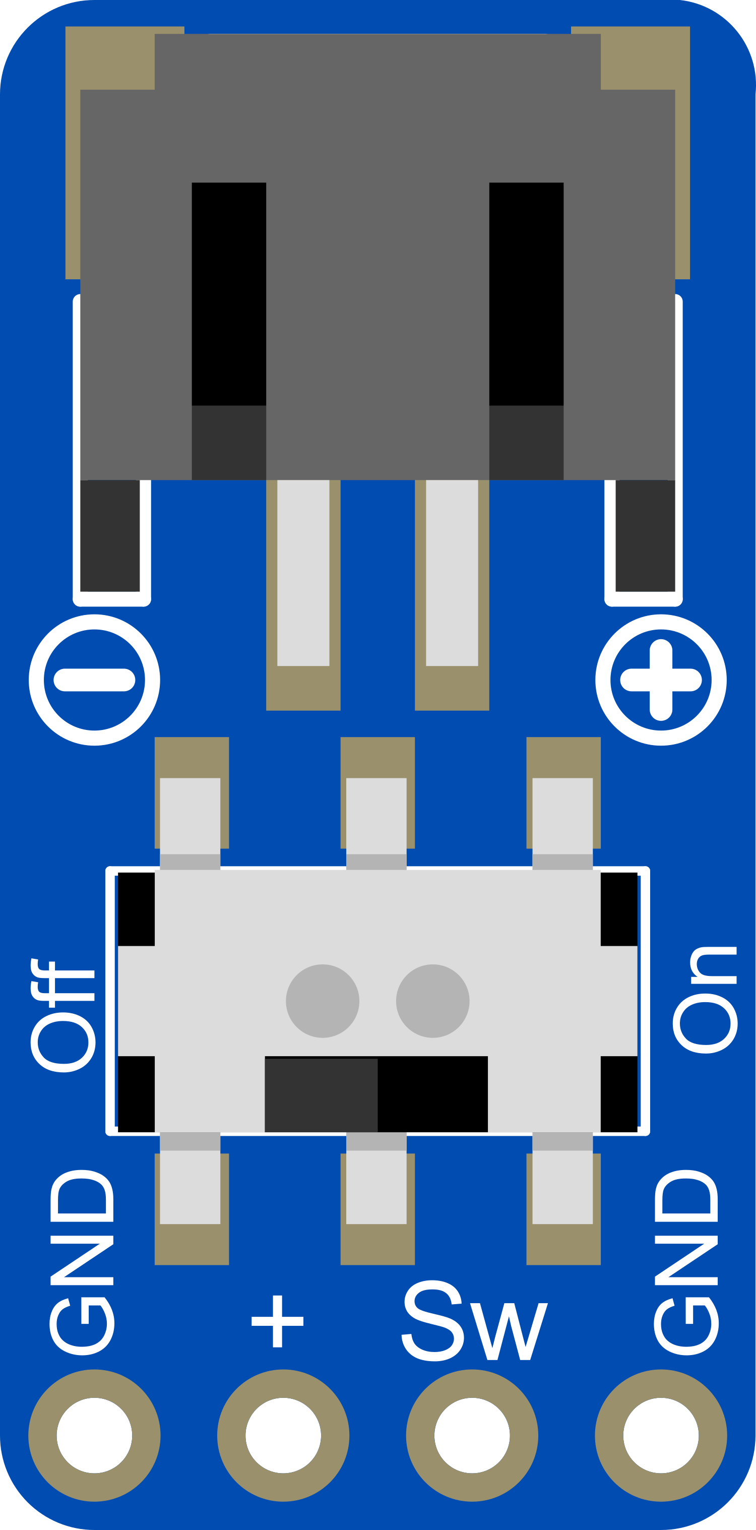
The Adafruit Switched JST Breakout is a versatile and user-friendly breakout board designed for hobbyists, engineers, and makers. This breakout board simplifies the process of connecting to devices with JST connectors, providing a switch to control the power supply to the connected device. It is commonly used in portable electronics, battery connections, and in projects where controlled power distribution is required.
Explore Projects Built with Adafruit Switched JST Breakout
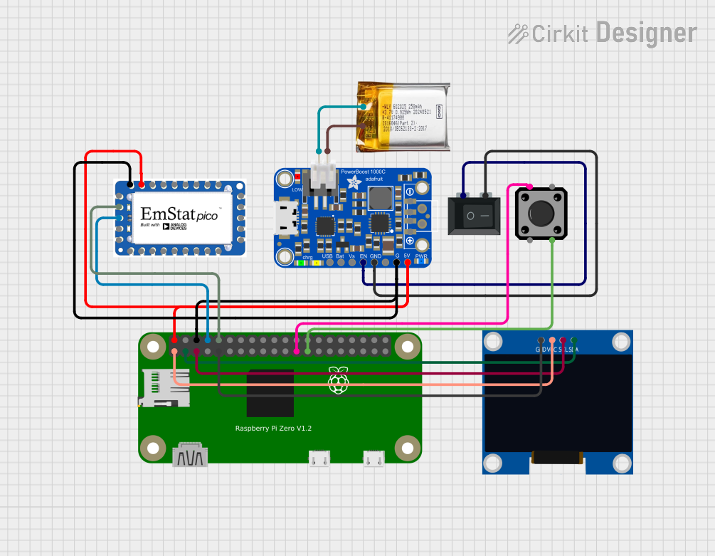

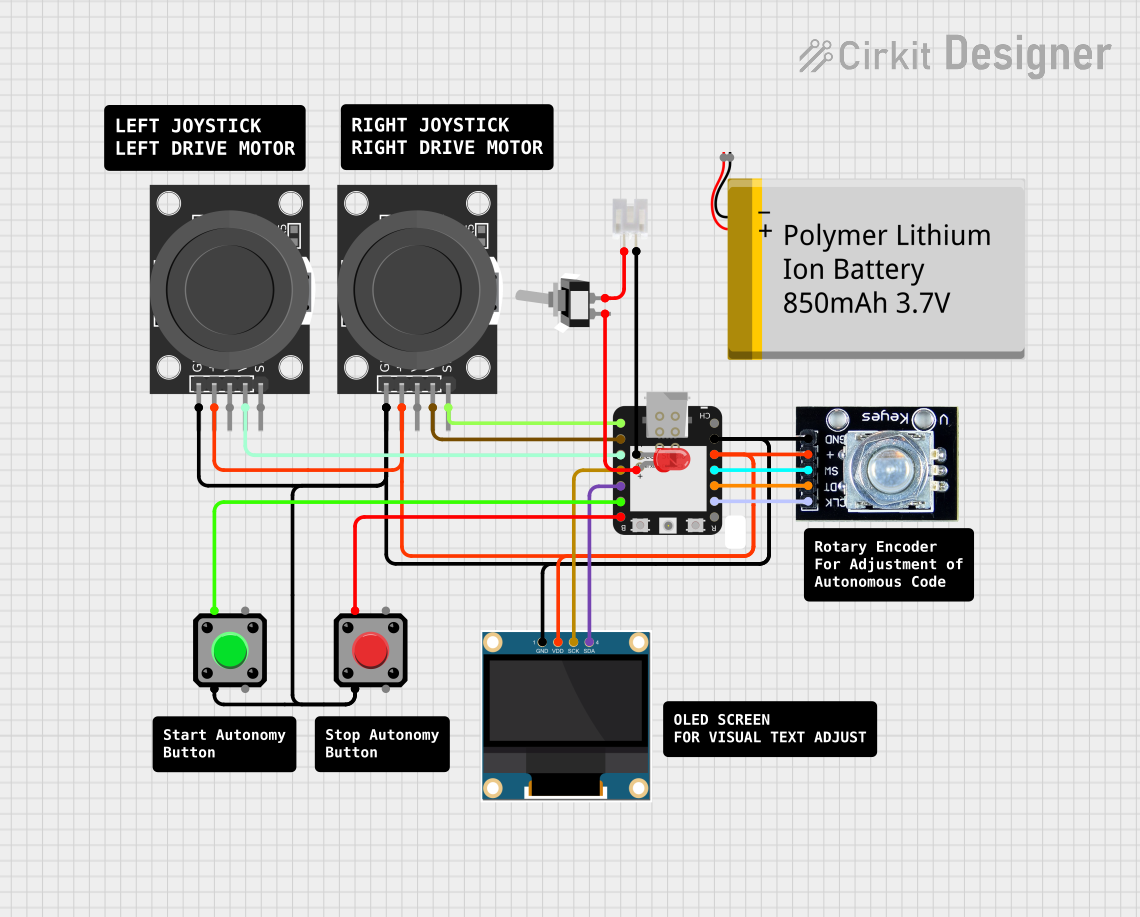
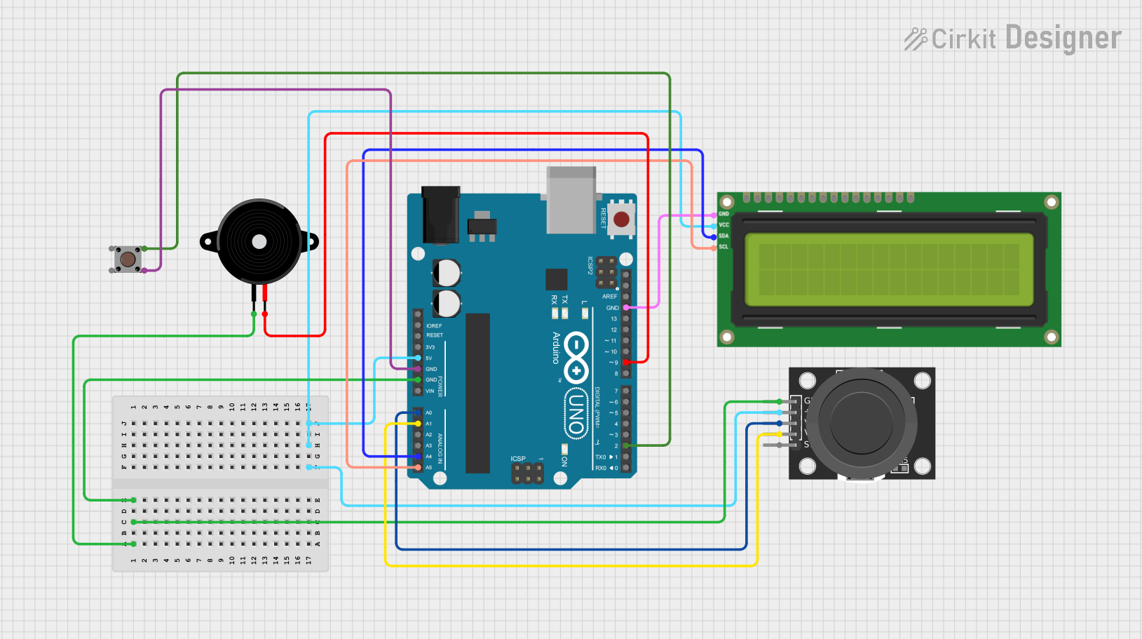
Explore Projects Built with Adafruit Switched JST Breakout
Common Applications
- Battery charging and power management
- Portable electronic projects
- Robotics and remote-controlled devices
- Prototyping with components that use JST connectors
Technical Specifications
Key Technical Details
- Voltage Rating: 3.3V to 5V
- Current Rating: Up to 2A
- Switch Type: Slide switch for power control
- Connector Type: JST PH 2-pin
- Dimensions: 25.3mm x 12.7mm x 4.7mm
Pin Configuration and Descriptions
| Pin Number | Description | Notes |
|---|---|---|
| 1 | VOUT | Voltage output when switched on |
| 2 | GND | Ground connection |
Usage Instructions
Connecting to a Circuit
- Power Input: Connect a power source to the JST connector on the breakout board. Ensure the voltage is within the specified range.
- Power Output: Use the VOUT and GND pins to connect to your device or component. The power will be controlled by the switch.
- Switching: Slide the switch to the ON position to provide power to the connected device. Slide it to the OFF position to cut off the power.
Important Considerations and Best Practices
- Voltage Compatibility: Always verify that the voltage of your power source matches the requirements of the connected device.
- Current Limitations: Do not exceed the 2A current rating to prevent damage to the breakout board or the connected device.
- Secure Connections: Ensure all connections are secure and free from shorts to prevent accidental damage.
- Mounting: If the breakout board is to be mounted, ensure it is securely attached to your project to prevent movement and potential disconnections.
Example Code for Arduino UNO
// Example code to control Adafruit Switched JST Breakout with Arduino UNO

void setup() {
  pinMode(13, OUTPUT); // Set the Arduino pin 13 as output
}

void loop() {
  digitalWrite(13, HIGH); // Turn on the connected device
  delay(1000);            // Wait for 1 second
  digitalWrite(13, LOW);  // Turn off the connected device
  delay(1000);            // Wait for 1 second
}
Note: This example assumes that the VOUT from the Adafruit Switched JST Breakout is connected to pin 13 on the Arduino UNO. The switch on the breakout board must be in the ON position for the code to control the power.
Troubleshooting and FAQs
Common Issues
- Device Not Powering On: Ensure the switch is in the ON position and that all connections are secure.
- Intermittent Power: Check for loose connections or potential shorts in the wiring.
- Exceeding Current Rating: If the device draws more than 2A, the breakout board may overheat or fail. Ensure the current draw is within limits.
Solutions and Tips
- Secure Wiring: Use heat shrink tubing or electrical tape to secure connections and prevent shorts.
- Power Source: Use a regulated power supply to prevent voltage spikes that could damage the breakout board or connected device.
- Inspection: Regularly inspect the breakout board for signs of wear or damage, especially if used in high-vibration environments.
FAQs
Q: Can I use this breakout board with a 3.7V LiPo battery? A: Yes, the Adafruit Switched JST Breakout can handle voltages from 3.3V to 5V, making it suitable for use with a 3.7V LiPo battery.
Q: Is it possible to control the switch electronically? A: The switch is a manual slide switch and is not designed to be controlled electronically. However, you can use a transistor or relay in conjunction with the breakout board to control power electronically.
Q: How do I know if the power is on? A: The breakout board does not have an indicator LED. You will need to use a multimeter to check for voltage at the VOUT pin or observe the operation of the connected device.