
Cirkit Designer LogoCirkit DesignerYour all-in-one circuit design IDE Launch Cirkit Designer App

How to Use CH32V003F4P6: Examples, Pinouts, and Specs

Image of CH32V003F4P6Design with CH32V003F4P6 in Cirkit Designer

Introduction

The CH32V003F4P6 is a low-power 32-bit microcontroller developed by WCH. It is based on the RISC-V architecture and operates at a maximum clock speed of 48 MHz. This microcontroller is equipped with 4 KB of SRAM and 16 KB of flash memory, making it suitable for a wide range of embedded applications. Its compact design, low power consumption, and versatile I/O interfaces make it ideal for IoT devices, industrial control systems, and consumer electronics.

Explore Projects Built with CH32V003F4P6

Use Cirkit Designer to design, explore, and prototype these projects online. Some projects support real-time simulation. Click "Open Project" to start designing instantly!
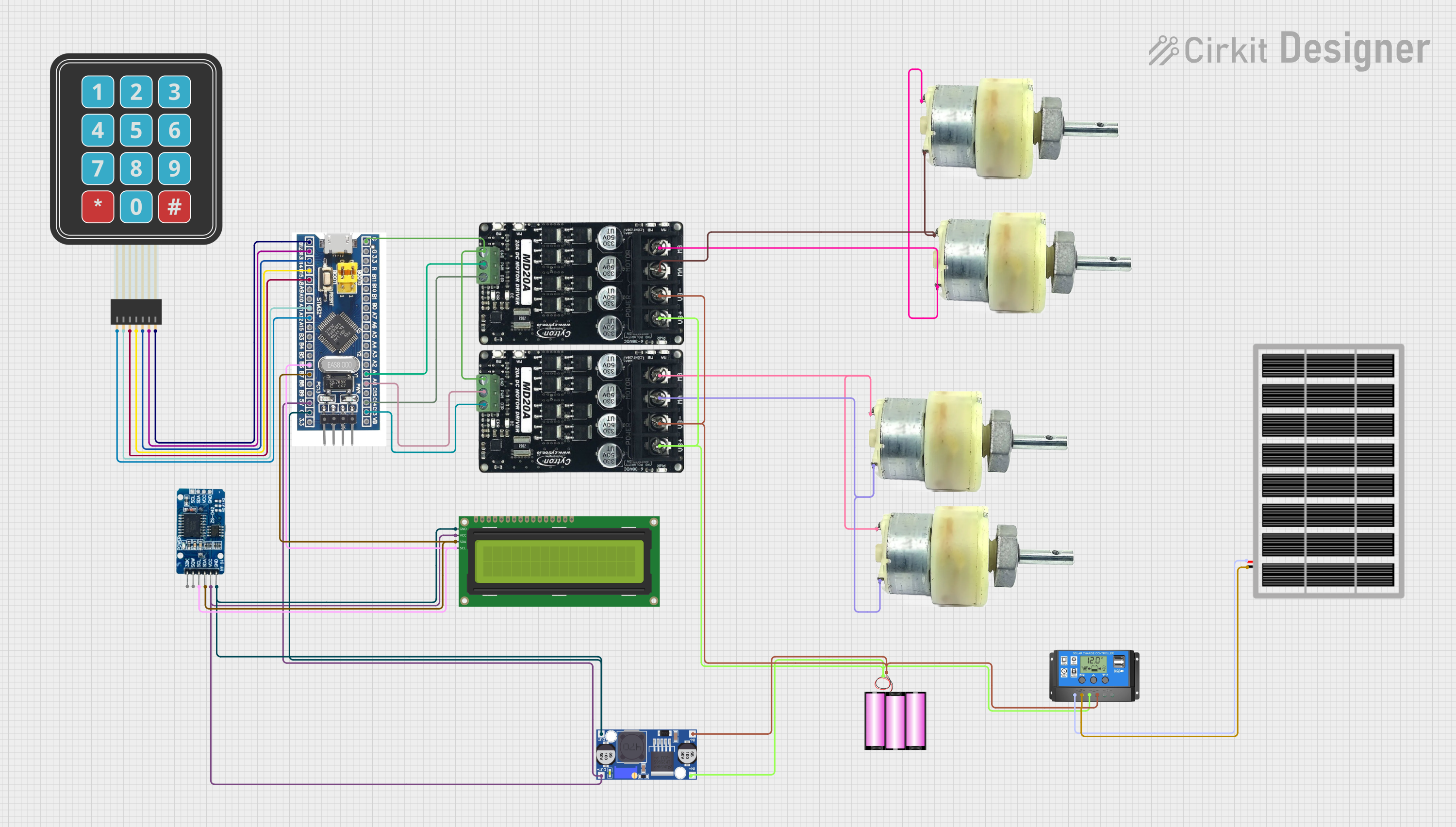
Image of Solar-Powered STM32-Based Automation System with Matrix Keypad and RTC: A project utilizing CH32V003F4P6 in a practical application
Solar-Powered STM32-Based Automation System with Matrix Keypad and RTC

This circuit features an STM32F103C8T6 microcontroller interfaced with a membrane matrix keypad for input, an RTC DS3231 for real-time clock functionality, and a 16x2 I2C LCD for display. It controls four 12V geared motors through two MD20 CYTRON motor drivers, with the motor power supplied by a 12V battery regulated by a buck converter. The battery is charged via a solar panel connected through a solar charge controller, ensuring a renewable energy source for the system.

Open Project in Cirkit Designer
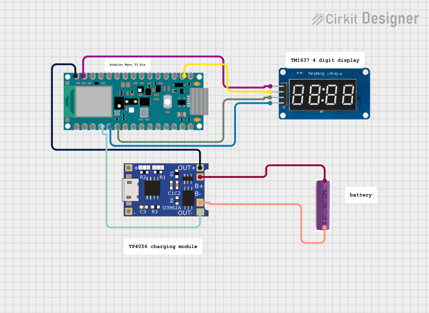
Image of Arduino Nano 33 BLE Battery-Powered Display Interface: A project utilizing CH32V003F4P6 in a practical application
Arduino Nano 33 BLE Battery-Powered Display Interface

This circuit features a Nano 33 BLE microcontroller interfaced with a TM1637 4-digit 7-segment display for information output, powered by a 3.7V battery managed by a TP4056 charging module. The microcontroller communicates with the display to present data, while the TP4056 ensures the battery is charged safely and provides power to the system.

Open Project in Cirkit Designer
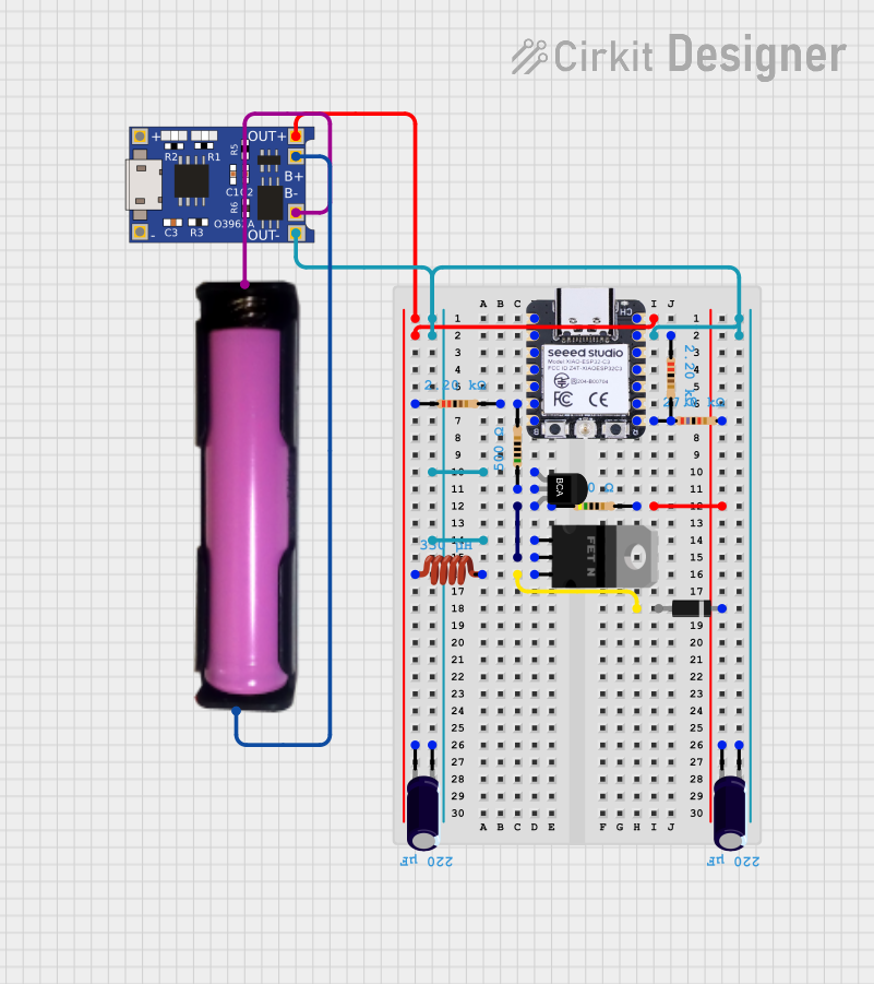
Common Applications

Technical Specifications

Key Technical Details

Parameter Specification
Architecture RISC-V
Core 32-bit
Maximum Clock Speed 48 MHz
Flash Memory 16 KB
SRAM 4 KB
Operating Voltage 2.7V to 5.5V
GPIO Pins Up to 18
Communication Interfaces UART, I²C, SPI
Timers 2 x 16-bit timers
ADC 1 x 10-bit ADC (up to 8 channels)
Power Consumption Low power, suitable for battery use
Package Type SOP-16

Pin Configuration and Descriptions

The CH32V003F4P6 is available in a 16-pin SOP package. Below is the pin configuration:

Pin Number Pin Name Function Description
1 VDD Power Supply Positive power supply (2.7V to 5.5V)
2 PA0 GPIO/ADC Channel 0 General-purpose I/O or ADC input
3 PA1 GPIO/ADC Channel 1 General-purpose I/O or ADC input
4 PA2 GPIO/USART TX General-purpose I/O or UART transmit
5 PA3 GPIO/USART RX General-purpose I/O or UART receive
6 PA4 GPIO/ADC Channel 4 General-purpose I/O or ADC input
7 PA5 GPIO/ADC Channel 5 General-purpose I/O or ADC input
8 PA6 GPIO/SPI SCK General-purpose I/O or SPI clock
9 PA7 GPIO/SPI MISO General-purpose I/O or SPI MISO
10 PA8 GPIO/SPI MOSI General-purpose I/O or SPI MOSI
11 PA9 GPIO/I²C SCL General-purpose I/O or I²C clock
12 PA10 GPIO/I²C SDA General-purpose I/O or I²C data
13 PA11 GPIO General-purpose I/O
14 PA12 GPIO General-purpose I/O
15 GND Ground Ground connection
16 NRST Reset Active-low reset pin

Usage Instructions

Using the CH32V003F4P6 in a Circuit

  1. Power Supply: Connect the VDD pin to a stable power source (2.7V to 5.5V) and the GND pin to ground.
  2. Reset: Use the NRST pin to reset the microcontroller. This pin should be pulled high during normal operation.
  3. I/O Configuration: Configure the GPIO pins as input or output based on your application. Unused pins should be left floating or pulled to a known state.
  4. Communication Interfaces:
    • Use PA2 and PA3 for UART communication.
    • Use PA6, PA7, and PA8 for SPI communication.
    • Use PA9 and PA10 for I²C communication.
  5. ADC Usage: Connect analog signals to the ADC pins (PA0 to PA7) for analog-to-digital conversion.

Important Considerations

Example: Interfacing with Arduino UNO

The CH32V003F4P6 can be programmed and interfaced with an Arduino UNO using UART. Below is an example code snippet for communication:

// Arduino UNO code to communicate with CH32V003F4P6 via UART
void setup() {
  Serial.begin(9600); // Initialize UART at 9600 baud rate
  Serial.println("Arduino to CH32V003F4P6 Communication Started");
}

void loop() {
  // Send data to CH32V003F4P6
  Serial.println("Hello CH32V003F4P6!");
  delay(1000); // Wait for 1 second

  // Check if data is received from CH32V003F4P6
  if (Serial.available() > 0) {
    String receivedData = Serial.readString();
    Serial.print("Received: ");
    Serial.println(receivedData);
  }
}

Troubleshooting and FAQs

Common Issues and Solutions

  1. Microcontroller Not Powering On:

    • Cause: Incorrect power supply voltage.
    • Solution: Ensure the VDD pin is supplied with 2.7V to 5.5V and the GND pin is properly connected.
  2. No UART Communication:

    • Cause: Incorrect baud rate or wiring.
    • Solution: Verify the baud rate settings and ensure TX and RX pins are correctly connected.
  3. ADC Not Working:

    • Cause: Improper configuration or noisy input signal.
    • Solution: Check the ADC configuration and ensure the input signal is within the ADC range.
  4. Microcontroller Not Resetting:

    • Cause: NRST pin not pulled low.
    • Solution: Ensure the NRST pin is momentarily pulled low to reset the microcontroller.

FAQs