How to Use IRF3710: Examples, Pinouts, and Specs
Introduction
The IRF3710 is an N-channel MOSFET manufactured by Infineon Technologies. It is designed for high-speed switching applications and offers low on-resistance, high current handling capabilities, and excellent thermal performance. This makes it an ideal choice for power management, motor control, DC-DC converters, and other high-efficiency power applications.
Explore Projects Built with IRF3710


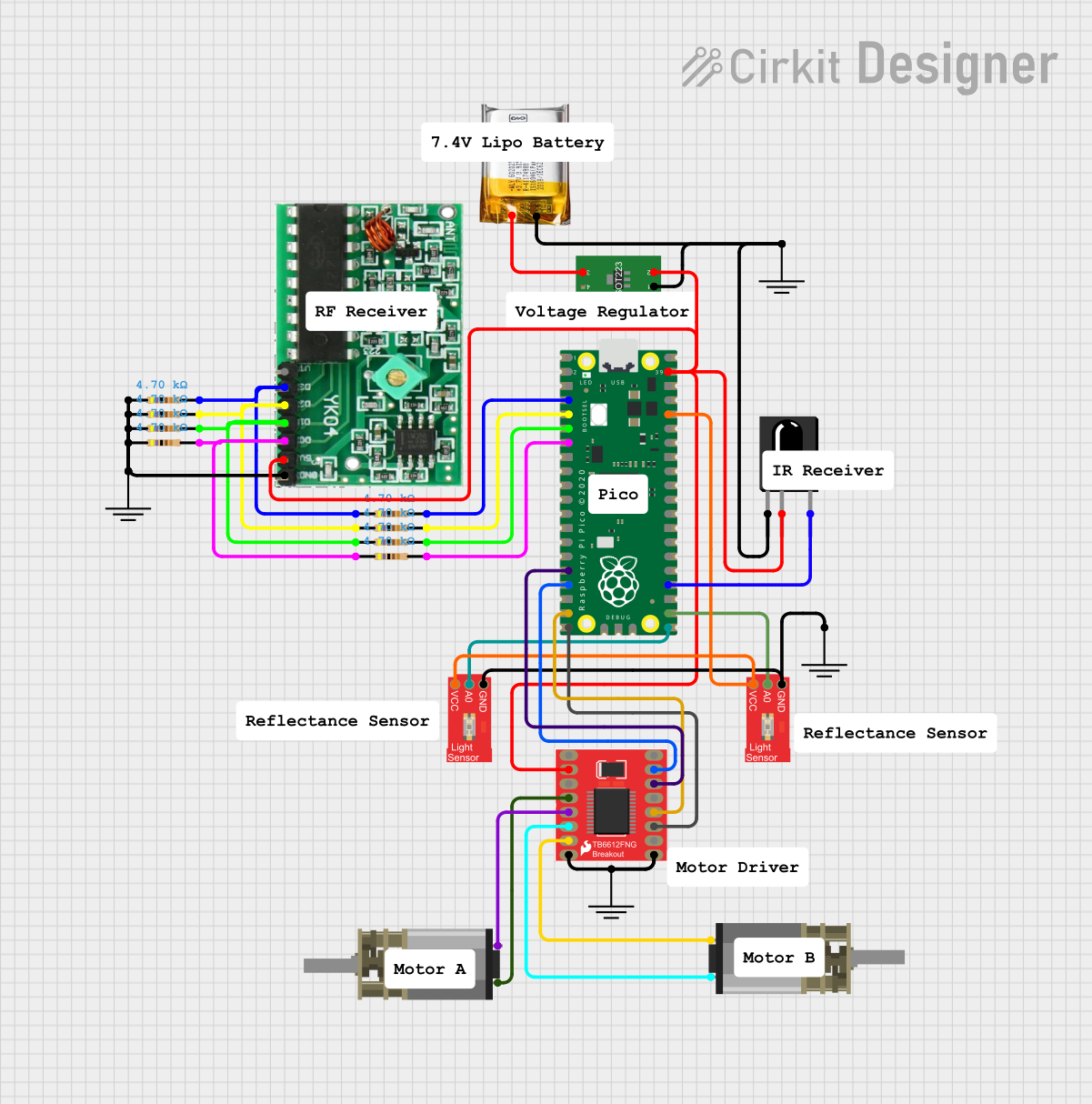
Explore Projects Built with IRF3710
Common Applications and Use Cases
- Motor control circuits
- DC-DC converters
- Power management in industrial and consumer electronics
- High-speed switching in power supplies
- Battery management systems
Technical Specifications
The IRF3710 is a robust and efficient MOSFET with the following key specifications:
| Parameter | Value |
|---|---|
| Manufacturer | Infineon Technologies |
| Part Number | IRF3710 |
| Type | N-Channel MOSFET |
| Maximum Drain-Source Voltage (VDS) | 100V |
| Maximum Gate-Source Voltage (VGS) | ±20V |
| Continuous Drain Current (ID) | 57A (at 25°C) |
| Pulsed Drain Current (IDM) | 230A |
| Power Dissipation (PD) | 200W (at 25°C) |
| On-Resistance (RDS(on)) | 23mΩ (typical at VGS = 10V) |
| Gate Threshold Voltage (VGS(th)) | 2.0V - 4.0V |
| Total Gate Charge (Qg) | 63nC (typical) |
| Operating Temperature Range | -55°C to +175°C |
| Package Type | TO-220 |
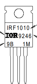
Pin Configuration and Descriptions
The IRF3710 is typically available in a TO-220 package with three pins. The pin configuration is as follows:
| Pin Number | Pin Name | Description |
|---|---|---|
| 1 | Gate (G) | Controls the MOSFET switching operation |
| 2 | Drain (D) | Current flows from drain to source |
| 3 | Source (S) | Connected to the ground or load |
Usage Instructions
How to Use the IRF3710 in a Circuit
- Gate Drive Voltage: Ensure the gate voltage (VGS) is within the recommended range (typically 10V for full enhancement). A gate resistor (e.g., 10Ω) can be used to limit inrush current and prevent damage to the gate.
- Load Connection: Connect the load between the drain and the positive supply voltage. The source is typically connected to ground.
- Heat Dissipation: Use a heatsink or proper thermal management to dissipate heat, especially when operating at high currents.
- Protection: Add a flyback diode across inductive loads (e.g., motors) to protect the MOSFET from voltage spikes during switching.
Example Circuit
Below is an example of using the IRF3710 to control a DC motor with an Arduino UNO:
Circuit Diagram
- Gate: Connected to an Arduino digital pin (e.g., D9) through a 10Ω resistor.
- Drain: Connected to one terminal of the motor.
- Source: Connected to ground.
- Motor: The other terminal is connected to the positive supply voltage.
- Flyback Diode: Place a diode (e.g., 1N4007) across the motor terminals to protect the MOSFET.
Arduino Code Example
// Example code to control a DC motor using the IRF3710 MOSFET
// Connect the MOSFET gate to pin 9 of the Arduino through a 10Ω resistor

const int motorPin = 9; // Pin connected to the MOSFET gate

void setup() {
  pinMode(motorPin, OUTPUT); // Set the motor pin as an output
}

void loop() {
  analogWrite(motorPin, 128); // Set motor speed to 50% (PWM value: 128)
  delay(5000);               // Run motor for 5 seconds

  analogWrite(motorPin, 0);  // Turn off the motor
  delay(5000);               // Wait for 5 seconds
}
Important Considerations and Best Practices
- Gate Drive Requirements: Ensure the gate voltage is sufficient to fully turn on the MOSFET (typically 10V for the IRF3710).
- Thermal Management: Use a heatsink or active cooling if the MOSFET operates at high currents or in high-temperature environments.
- Switching Speed: Minimize gate capacitance effects by using a proper gate driver circuit for high-speed switching applications.
- Voltage Spikes: Protect the MOSFET from voltage transients using snubber circuits or TVS diodes.
Troubleshooting and FAQs
Common Issues and Solutions
MOSFET Overheating
- Cause: Insufficient heatsinking or excessive current.
- Solution: Use a larger heatsink, improve ventilation, or reduce the load current.
MOSFET Not Switching Properly
- Cause: Insufficient gate drive voltage.
- Solution: Ensure the gate voltage is at least 10V for full enhancement.
MOSFET Fails or Shorts
- Cause: Voltage spikes from inductive loads.
- Solution: Add a flyback diode across the load to suppress voltage spikes.
Low Efficiency in Circuit
- Cause: High on-resistance or poor gate drive.
- Solution: Verify the gate drive voltage and ensure the MOSFET is fully enhanced.
FAQs
Q1: Can the IRF3710 be used with a 3.3V microcontroller?
A1: The IRF3710 requires a gate voltage of at least 10V for full enhancement. A 3.3V microcontroller may not provide sufficient voltage. Use a gate driver circuit to step up the voltage.
Q2: What is the maximum current the IRF3710 can handle?
A2: The IRF3710 can handle up to 57A continuously at 25°C, but proper thermal management is required to avoid overheating.
Q3: Can the IRF3710 be used for AC applications?
A3: The IRF3710 is primarily designed for DC applications. For AC applications, consider using an H-bridge circuit or a dedicated AC switch.
Q4: How do I protect the IRF3710 from damage?
A4: Use a flyback diode for inductive loads, ensure proper gate drive voltage, and implement thermal management to prevent overheating.