How to Use Relay 8 Pin: Examples, Pinouts, and Specs
Introduction
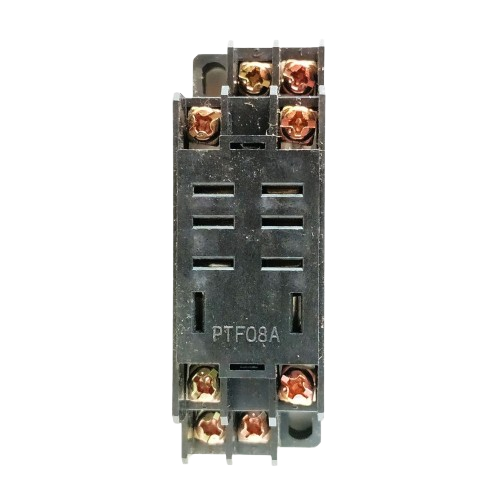
The Omron Relay (8 Pin) is an electromechanical switch designed to control circuits by opening and closing contacts in response to an electrical signal. This relay allows users to control high voltage or high current devices using a low voltage signal, making it an essential component in automation, home appliances, and industrial control systems.
Explore Projects Built with Relay 8 Pin


Explore Projects Built with Relay 8 Pin
Common Applications and Use Cases
- Home Automation: Controlling lights, fans, and other appliances.
- Industrial Control Systems: Managing motors, pumps, and heavy machinery.
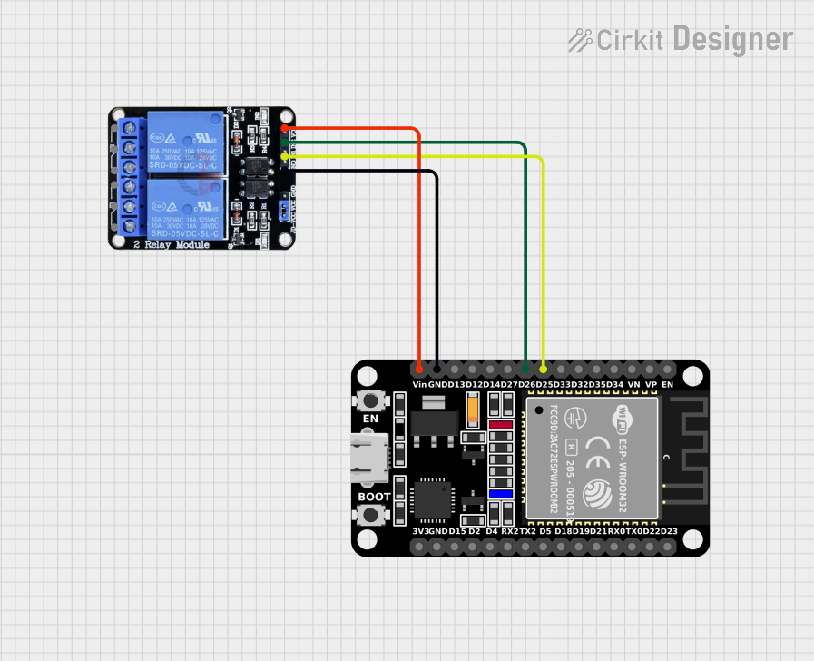
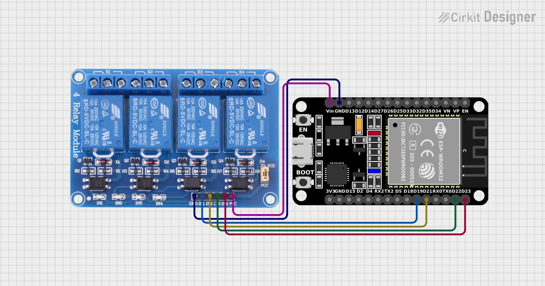
- Microcontroller Projects: Interfacing with Arduino, Raspberry Pi, or other microcontrollers.
- Safety Systems: Emergency shutdowns and circuit isolation.
- Automotive Applications: Switching headlights, horns, and other vehicle systems.
Technical Specifications
Below are the key technical details for the Omron Relay (8 Pin):
| Parameter | Value |
|---|---|
| Manufacturer | Omron |
| Part ID | Relay |
| Contact Configuration | SPDT (Single Pole Double Throw) or DPDT (Double Pole Double Throw) |
| Coil Voltage | 5V, 12V, or 24V (depending on model) |
| Contact Voltage Rating | Up to 250V AC / 30V DC |
| Contact Current Rating | Up to 10A |
| Coil Resistance | Varies by model (e.g., 400Ω for 12V coil) |
| Switching Time | Typically 10ms (operate) / 5ms (release) |
| Insulation Resistance | ≥ 100MΩ at 500V DC |
| Dielectric Strength | 1500V AC (coil to contact) |
| Operating Temperature | -40°C to +85°C |
| Dimensions | Varies by model (e.g., 28mm x 12mm x 15mm) |
Pin Configuration and Descriptions
The Omron Relay (8 Pin) typically has the following pin configuration:
| Pin Number | Name | Description |
|---|---|---|
| 1 | Coil (+) | Positive terminal of the relay coil. |
| 2 | Coil (-) | Negative terminal of the relay coil. |
| 3 | Common (COM1) | Common terminal for the first contact set. |
| 4 | Normally Open (NO1) | Normally open terminal for the first contact set. |
| 5 | Normally Closed (NC1) | Normally closed terminal for the first contact set. |
| 6 | Common (COM2) | Common terminal for the second contact set (if DPDT). |
| 7 | Normally Open (NO2) | Normally open terminal for the second contact set (if DPDT). |
| 8 | Normally Closed (NC2) | Normally closed terminal for the second contact set (if DPDT). |
Note: For SPDT relays, only one set of contacts (COM, NO, NC) is present.
Usage Instructions
How to Use the Relay in a Circuit
- Power the Coil: Connect the relay coil pins (1 and 2) to a power source matching the relay's rated coil voltage (e.g., 5V, 12V, or 24V).
- Control the Load:
- Connect the load to the Common (COM) and either the Normally Open (NO) or Normally Closed (NC) terminals.
- Use the NO terminal if you want the load to be powered only when the relay is activated.
- Use the NC terminal if you want the load to be powered when the relay is not activated.
- Drive the Relay:
- Use a transistor or relay driver IC to control the relay coil with a low voltage signal from a microcontroller.
- Add a flyback diode across the coil terminals to protect the circuit from voltage spikes when the relay is deactivated.
Example Circuit with Arduino UNO
Below is an example of how to control the relay using an Arduino UNO:
// Example: Controlling an 8-pin relay with Arduino UNO
// Pin 7 of Arduino is connected to the relay control pin (via a transistor).

const int relayPin = 7; // Define the Arduino pin connected to the relay

void setup() {
  pinMode(relayPin, OUTPUT); // Set the relay pin as an output
  digitalWrite(relayPin, LOW); // Ensure the relay is off initially
}

void loop() {
  digitalWrite(relayPin, HIGH); // Turn the relay on
  delay(1000); // Keep it on for 1 second
  digitalWrite(relayPin, LOW); // Turn the relay off
  delay(1000); // Keep it off for 1 second
}
Important Considerations and Best Practices
- Voltage Matching: Ensure the coil voltage matches the relay's rated voltage to avoid damage.
- Flyback Diode: Always use a flyback diode across the coil to prevent voltage spikes.
- Contact Ratings: Do not exceed the relay's contact voltage and current ratings.
- Isolation: Use optocouplers or isolation circuits when interfacing with sensitive microcontrollers.
- Mounting: Secure the relay properly to avoid vibrations or loose connections.
Troubleshooting and FAQs
Common Issues and Solutions
| Issue | Possible Cause | Solution |
|---|---|---|
| Relay does not activate | Insufficient coil voltage or current | Verify the power supply and ensure it matches the relay's coil specifications. |
| Relay chatters or buzzes | Unstable power supply | Use a stable power source or add a capacitor across the power supply terminals. |
| Load does not turn on/off | Incorrect wiring of NO/NC terminals | Double-check the wiring and ensure the load is connected to the correct terminals. |
| Microcontroller resets when relay activates | Voltage spike from the relay coil | Add a flyback diode across the relay coil terminals. |
| Relay overheats | Exceeding contact current rating | Ensure the load current is within the relay's rated capacity. |
FAQs
Can I use this relay with a 3.3V microcontroller?
- Yes, but you will need a transistor or relay driver circuit to step up the control voltage to match the relay's coil voltage.
What is the purpose of the flyback diode?
- The flyback diode protects the circuit from voltage spikes generated when the relay coil is de-energized.
Can I use this relay for AC loads?
- Yes, the relay can handle AC loads up to its rated voltage and current. Ensure proper insulation and safety precautions.
How do I know if the relay is SPDT or DPDT?
- Check the datasheet or inspect the pin configuration. SPDT relays have one set of COM, NO, and NC terminals, while DPDT relays have two sets.
By following this documentation, you can effectively integrate the Omron Relay (8 Pin) into your projects and troubleshoot common issues with ease.