Cirkit Designer Logo
Cirkit Designer
Your all-in-one circuit design IDE
Home / 
Component Documentation

How to Use 4X4 Membrane Matrix Keypad: Examples, Pinouts, and Specs

Image of 4X4 Membrane Matrix Keypad
Cirkit Designer LogoDesign with 4X4 Membrane Matrix Keypad in Cirkit Designer

Introduction

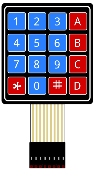
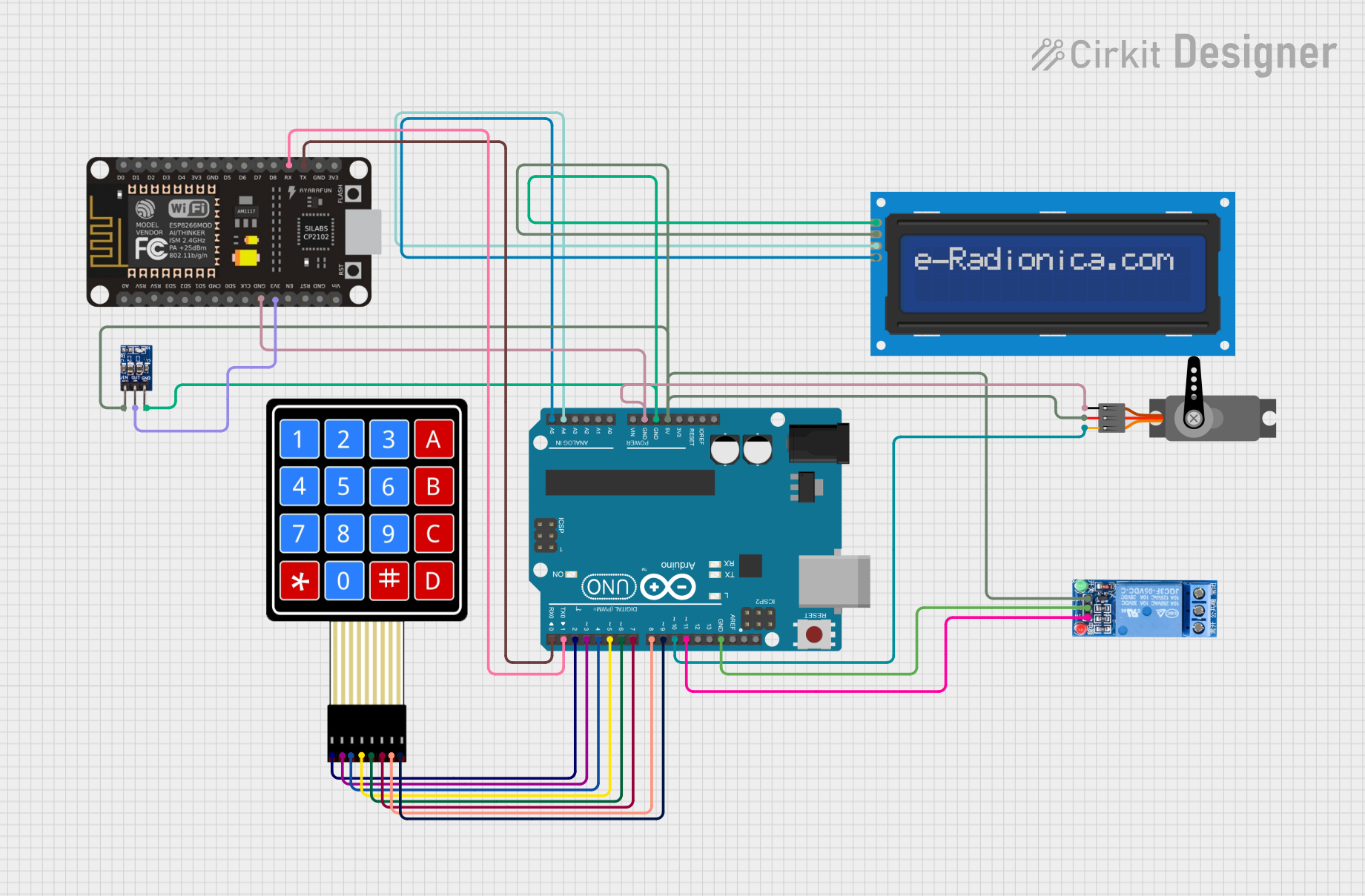
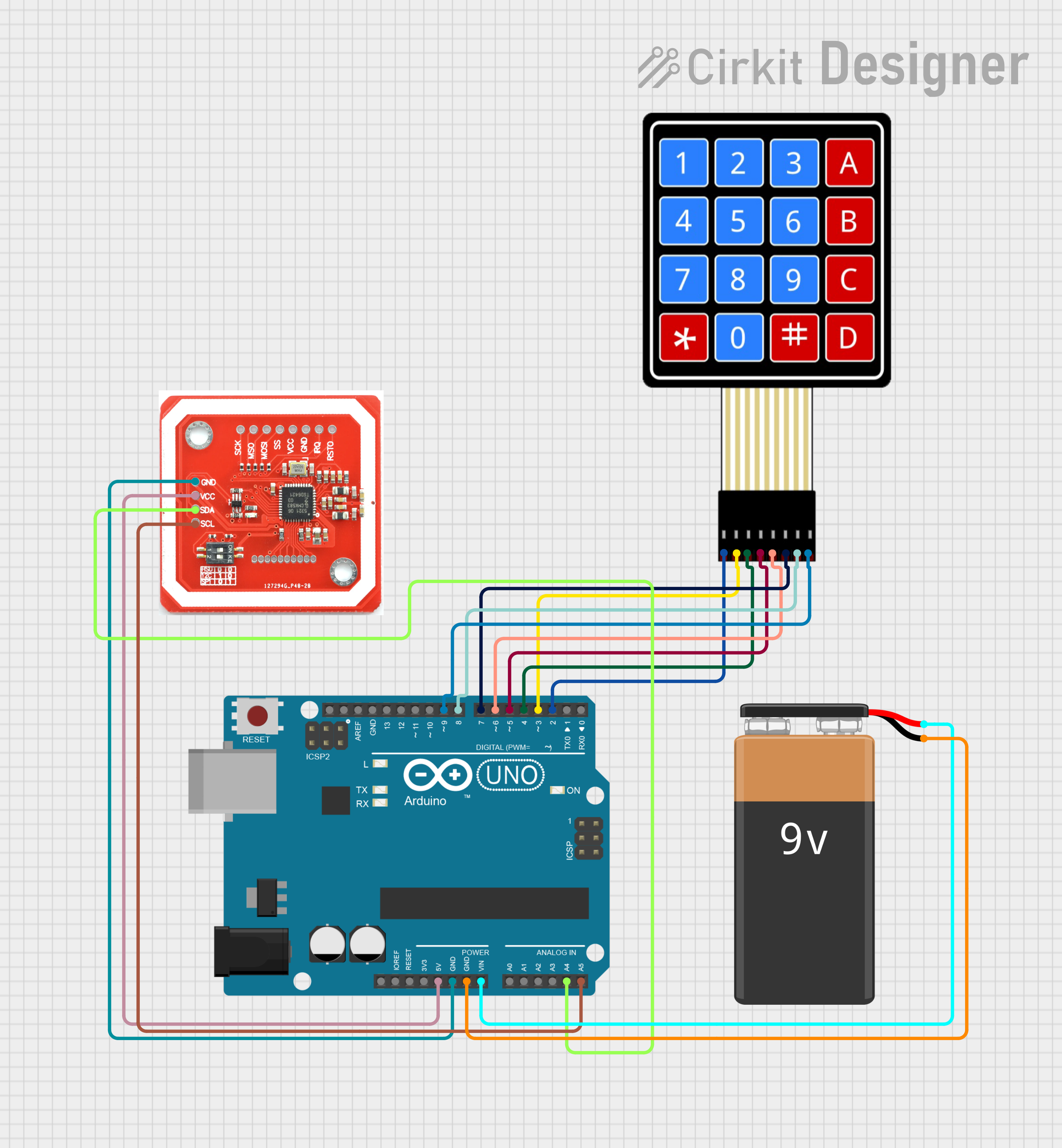
The 4X4 Membrane Matrix Keypad is a user input device manufactured by Parallax Inc., part number 27899. This keypad consists of 16 buttons arranged in a 4x4 grid, allowing for a compact and versatile method of capturing user input. It is commonly used in electronic projects such as security systems, telephone dial pads, and various control panels.

Explore Projects Built with 4X4 Membrane Matrix Keypad

Use Cirkit Designer to design, explore, and prototype these projects online. Some projects support real-time simulation. Click "Open Project" to start designing instantly!
Arduino UNO Based 4x4 Keypad Interface
Image of keypad: A project utilizing 4X4 Membrane Matrix Keypad in a practical application
This circuit connects a 4x4 membrane matrix keypad to an Arduino UNO microcontroller. The rows (R1-R4) and columns (C1-C4) of the keypad are wired to digital pins D9-D2 on the Arduino, respectively. The purpose of the circuit is to allow the Arduino to detect and process key presses from the keypad, which can be used for user input in various applications.
Cirkit Designer LogoOpen Project in Cirkit Designer
Arduino UNO Keypad-Controlled LED and Buzzer System with RTC and Bluetooth
Image of Uni: A project utilizing 4X4 Membrane Matrix Keypad in a practical application
This circuit is an Arduino-based keypad interface system that reads input from a 4x4 membrane matrix keypad and displays the pressed key on the serial monitor. It also includes a real-time clock (RTC) module, a Bluetooth module, and visual indicators using red and green LEDs. Additionally, a buzzer is controlled via an NPN transistor for audio feedback.
Cirkit Designer LogoOpen Project in Cirkit Designer
Arduino UNO and ESP8266-Based Smart Lock with Keypad and LCD Display
Image of Lock: A project utilizing 4X4 Membrane Matrix Keypad in a practical application
This circuit is a security system that uses a 4x4 membrane keypad to input a PIN, which is processed by an Arduino UNO. Upon entering the correct PIN, the system activates a servo motor and a relay, and displays status messages on a 16x2 I2C LCD screen. Additionally, an ESP8266 module is included for potential wireless communication.
Cirkit Designer LogoOpen Project in Cirkit Designer
Arduino UNO Based NFC Reader with Membrane Keypad Interface
Image of NFC_serial: A project utilizing 4X4 Membrane Matrix Keypad in a practical application
This circuit features an Arduino UNO connected to a 4x4 membrane matrix keypad, an NFC/RFID reader, and powered by a 9V battery. The Arduino is programmed to detect and display keypad inputs and read NFC tags, likely for an access control or identification system. The NFC/RFID reader communicates with the Arduino via I2C (using SDA and SCL lines), and the keypad is interfaced using digital IO pins.
Cirkit Designer LogoOpen Project in Cirkit Designer

Explore Projects Built with 4X4 Membrane Matrix Keypad

Use Cirkit Designer to design, explore, and prototype these projects online. Some projects support real-time simulation. Click "Open Project" to start designing instantly!
Image of keypad: A project utilizing 4X4 Membrane Matrix Keypad in a practical application
Arduino UNO Based 4x4 Keypad Interface
This circuit connects a 4x4 membrane matrix keypad to an Arduino UNO microcontroller. The rows (R1-R4) and columns (C1-C4) of the keypad are wired to digital pins D9-D2 on the Arduino, respectively. The purpose of the circuit is to allow the Arduino to detect and process key presses from the keypad, which can be used for user input in various applications.
Cirkit Designer LogoOpen Project in Cirkit Designer
Image of Uni: A project utilizing 4X4 Membrane Matrix Keypad in a practical application
Arduino UNO Keypad-Controlled LED and Buzzer System with RTC and Bluetooth
This circuit is an Arduino-based keypad interface system that reads input from a 4x4 membrane matrix keypad and displays the pressed key on the serial monitor. It also includes a real-time clock (RTC) module, a Bluetooth module, and visual indicators using red and green LEDs. Additionally, a buzzer is controlled via an NPN transistor for audio feedback.
Cirkit Designer LogoOpen Project in Cirkit Designer
Image of Lock: A project utilizing 4X4 Membrane Matrix Keypad in a practical application
Arduino UNO and ESP8266-Based Smart Lock with Keypad and LCD Display
This circuit is a security system that uses a 4x4 membrane keypad to input a PIN, which is processed by an Arduino UNO. Upon entering the correct PIN, the system activates a servo motor and a relay, and displays status messages on a 16x2 I2C LCD screen. Additionally, an ESP8266 module is included for potential wireless communication.
Cirkit Designer LogoOpen Project in Cirkit Designer
Image of NFC_serial: A project utilizing 4X4 Membrane Matrix Keypad in a practical application
Arduino UNO Based NFC Reader with Membrane Keypad Interface
This circuit features an Arduino UNO connected to a 4x4 membrane matrix keypad, an NFC/RFID reader, and powered by a 9V battery. The Arduino is programmed to detect and display keypad inputs and read NFC tags, likely for an access control or identification system. The NFC/RFID reader communicates with the Arduino via I2C (using SDA and SCL lines), and the keypad is interfaced using digital IO pins.
Cirkit Designer LogoOpen Project in Cirkit Designer

Common Applications and Use Cases

  • Numeric input for security keypads
  • Menu navigation for user interfaces
  • Control panels for electronics projects
  • Prototyping for embedded systems

Technical Specifications

Key Technical Details

  • Operating Voltage: 3.3V to 5V
  • Interface: 8-pin connector
  • Contact Bounce: <5ms
  • Actuation Force: 160-180g
  • Life Expectancy: 1 million operations per key

Pin Configuration and Descriptions

Pin Number Description
1 Row 1
2 Row 2
3 Row 3
4 Row 4
5 Column 1
6 Column 2
7 Column 3
8 Column 4

Usage Instructions

How to Use the Component in a Circuit

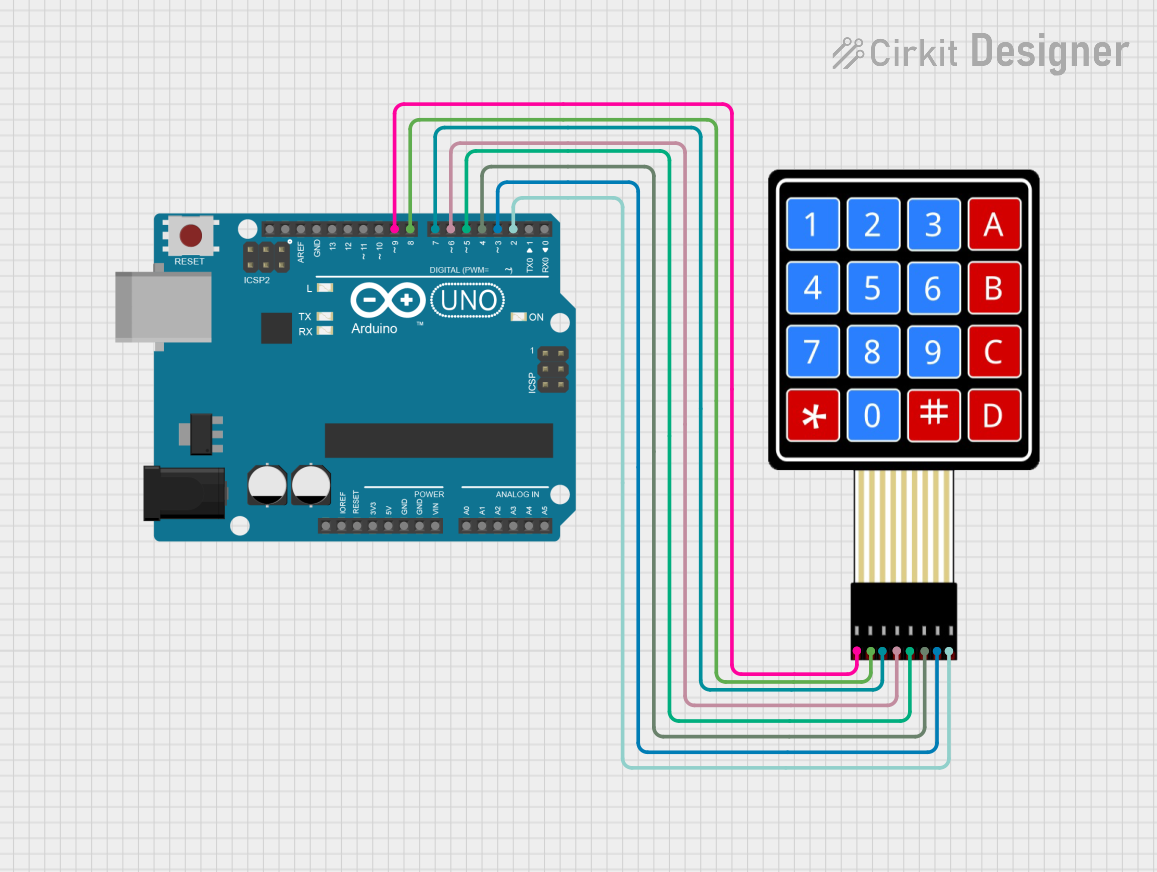
  1. Connect the row pins (1-4) to the digital input pins on your microcontroller.
  2. Connect the column pins (5-8) to the digital output pins on your microcontroller.
  3. Apply a pull-up resistor or enable the internal pull-up resistors on the microcontroller for the row pins.
  4. To detect a keypress, set one column to low and read the rows. If a key is pressed, the corresponding row will read low.
  5. Repeat the process for each column to determine the specific key pressed.

Important Considerations and Best Practices

  • Ensure that the voltage levels are compatible with your microcontroller to prevent damage.
  • Debounce the keys in software to avoid false readings due to contact bounce.
  • Use a keypad library if available for your platform to simplify programming.

Example Code for Arduino UNO

#include <Keypad.h>

const byte ROWS = 4; // Four rows
const byte COLS = 4; // Four columns

// Define the Keymap
char keys[ROWS][COLS] = {
  {'1','2','3','A'},
  {'4','5','6','B'},
  {'7','8','9','C'},
  {'*','0','#','D'}
};

// Connect keypad ROW0, ROW1, ROW2 and ROW3 to these Arduino pins.
byte rowPins[ROWS] = {9, 8, 7, 6};

// Connect keypad COL0, COL1, COL2 and COL3 to these Arduino pins.
byte colPins[COLS] = {5, 4, 3, 2};

// Create the Keypad
Keypad keypad = Keypad(makeKeymap(keys), rowPins, colPins, ROWS, COLS);

void setup() {
  Serial.begin(9600);
}

void loop() {
  char key = keypad.getKey();
  
  if (key) {
    Serial.println(key);
  }
}

Troubleshooting and FAQs

Common Issues Users Might Face

  • Keys not responding: Ensure all connections are secure and the pins are correctly configured in your code.
  • Multiple keys registering at once: This could be due to not using diodes for preventing ghosting or not properly debouncing the keys in software.
  • Inconsistent readings: Check for a stable power supply and ensure that the pull-up resistors are correctly configured.

Solutions and Tips for Troubleshooting

  • Double-check wiring against the pin configuration table.
  • Implement software debouncing to handle contact bounce.
  • Use a multimeter to verify the continuity of the keypad's traces if a button is not working.

FAQs

Q: Can I use this keypad with a 3.3V system? A: Yes, the keypad can operate at 3.3V, but ensure that the logic levels are compatible with your microcontroller.

Q: How can I prevent ghosting on the keypad? A: To prevent ghosting, you can use diodes on each button or ensure that no more than one key is pressed at a time.

Q: What is the best way to detect a long press on a key? A: In your code, you can measure the time between the key press and release events to determine a long press.

Q: How do I clean the keypad if a button becomes unresponsive? A: Gently wipe the surface with a soft, damp cloth. Avoid using harsh chemicals that may damage the membrane surface.