How to Use L9110: Examples, Pinouts, and Specs
Introduction
The L9110 is a dual H-bridge motor driver IC designed for controlling two DC motors or one stepper motor. It enables bidirectional control of motors, allowing them to rotate in both forward and reverse directions. Compact and efficient, the L9110 is widely used in robotics, automation, and other motor control applications. Its simplicity and low power consumption make it an excellent choice for hobbyists and professionals alike.
Explore Projects Built with L9110

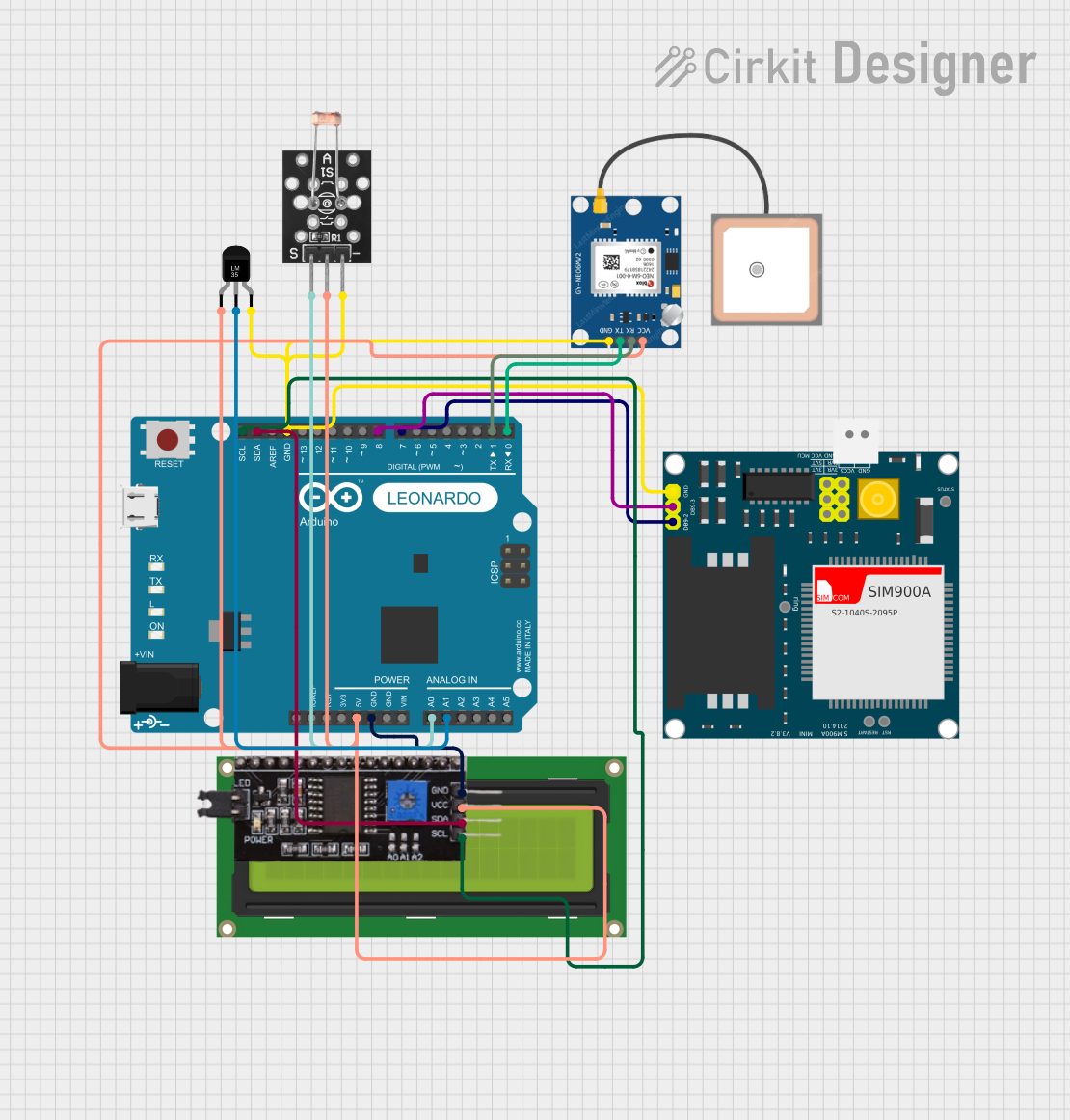

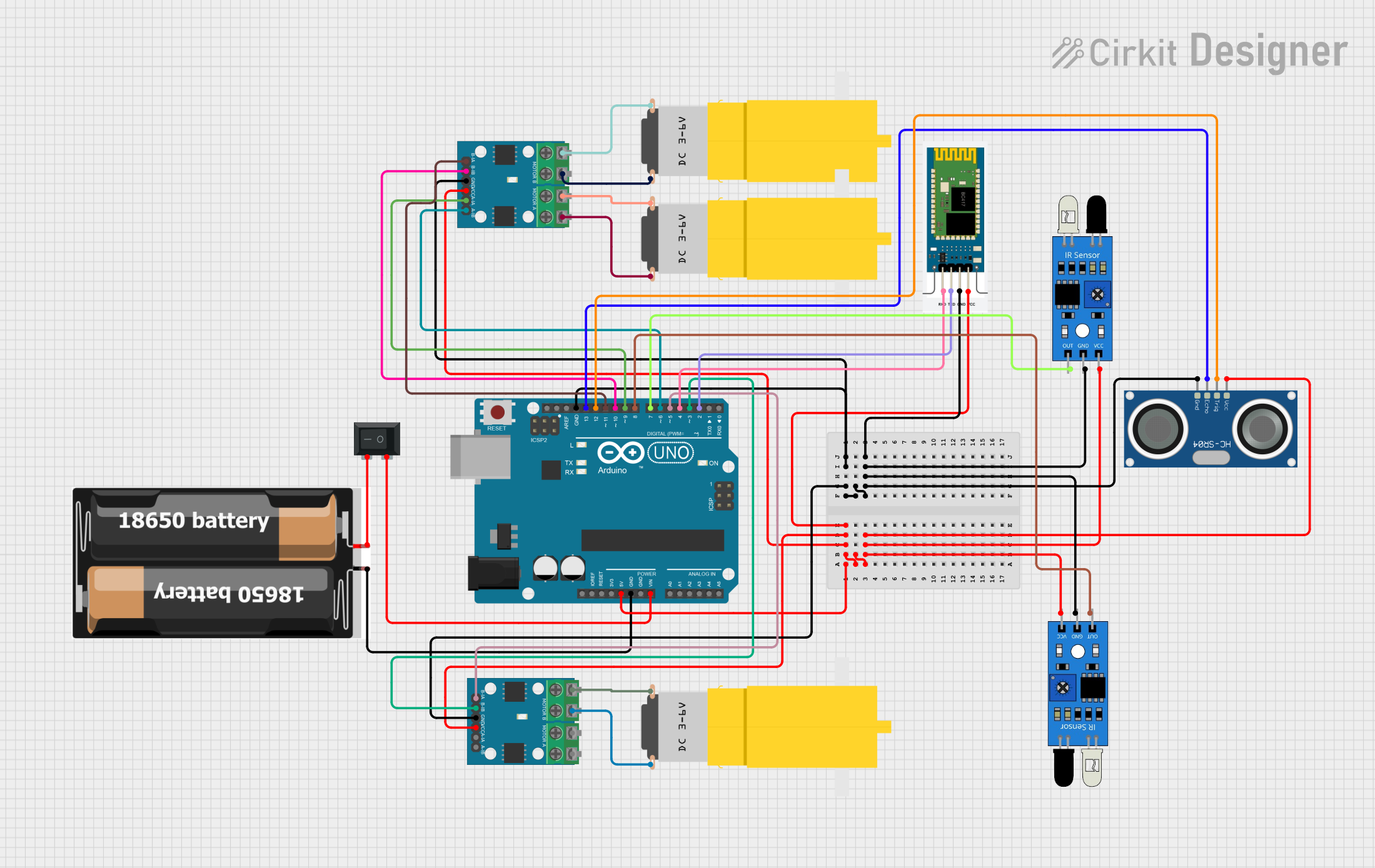
Explore Projects Built with L9110
Common Applications
- Robotics (e.g., motorized robots, robotic arms)
- Automation systems
- Small-scale conveyor belts
- Remote-controlled vehicles
- DIY motorized projects
Technical Specifications
The L9110 motor driver IC has the following key technical specifications:
| Parameter | Value |
|---|---|
| Operating Voltage | 2.5V to 12V |
| Output Current (per channel) | 800mA (continuous) |
| Peak Output Current | 1.5A |
| Logic Input Voltage | 0V to 5V |
| Number of Channels | 2 (dual H-bridge) |
| Control Logic | TTL/CMOS compatible |
| Operating Temperature | -40°C to +85°C |
| Package Type | DIP-8 or SOP-8 |
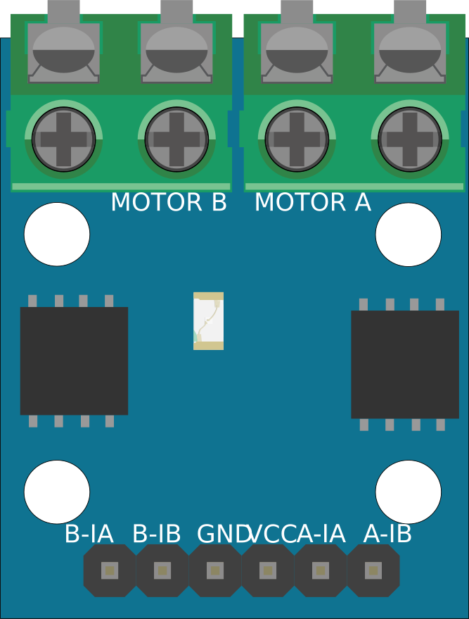
Pin Configuration and Descriptions
The L9110 IC has 8 pins, as described in the table below:
| Pin Number | Pin Name | Description |
|---|---|---|
| 1 | A-1A | Input signal for Motor A (controls direction) |
| 2 | A-1B | Input signal for Motor A (controls direction) |
| 3 | GND | Ground connection |
| 4 | VCC | Power supply for the IC (2.5V to 12V) |
| 5 | B-1A | Input signal for Motor B (controls direction) |
| 6 | B-1B | Input signal for Motor B (controls direction) |
| 7 | Motor B+ | Output terminal for Motor B |
| 8 | Motor A+ | Output terminal for Motor A |
Usage Instructions
How to Use the L9110 in a Circuit
- Power Supply: Connect the VCC pin to a power source (2.5V to 12V) and the GND pin to ground.
- Motor Connections:
- Connect the Motor A terminals to the Motor A+ pin and GND.
- Connect the Motor B terminals to the Motor B+ pin and GND.
- Control Signals:
- Use the A-1A and A-1B pins to control the direction of Motor A.
- Use the B-1A and B-1B pins to control the direction of Motor B.
- Apply a HIGH or LOW signal to these pins to set the motor's direction and speed.
- Logic Voltage: Ensure the control signals are within the logic voltage range (0V to 5V).
Important Considerations
- Current Limitation: Do not exceed the maximum continuous current rating of 800mA per channel to avoid overheating or damaging the IC.
- Heat Dissipation: If operating near the peak current, consider adding a heat sink or ensuring proper ventilation.
- Power Supply: Use a stable power supply to prevent voltage fluctuations that could affect motor performance.
- Decoupling Capacitors: Add a decoupling capacitor (e.g., 100µF) across the VCC and GND pins to reduce noise and stabilize the power supply.
Example: Using L9110 with Arduino UNO
Below is an example of how to control two DC motors using the L9110 and an Arduino UNO:
// Define motor control pins
const int motorA1 = 2; // Motor A control pin 1
const int motorA2 = 3; // Motor A control pin 2
const int motorB1 = 4; // Motor B control pin 1
const int motorB2 = 5; // Motor B control pin 2

void setup() {
  // Set motor control pins as outputs
  pinMode(motorA1, OUTPUT);
  pinMode(motorA2, OUTPUT);
  pinMode(motorB1, OUTPUT);
  pinMode(motorB2, OUTPUT);
}

void loop() {
  // Rotate Motor A forward
  digitalWrite(motorA1, HIGH);
  digitalWrite(motorA2, LOW);

  // Rotate Motor B backward
  digitalWrite(motorB1, LOW);
  digitalWrite(motorB2, HIGH);

  delay(2000); // Run motors for 2 seconds

  // Stop both motors
  digitalWrite(motorA1, LOW);
  digitalWrite(motorA2, LOW);
  digitalWrite(motorB1, LOW);
  digitalWrite(motorB2, LOW);

  delay(2000); // Wait for 2 seconds

  // Rotate Motor A backward
  digitalWrite(motorA1, LOW);
  digitalWrite(motorA2, HIGH);

  // Rotate Motor B forward
  digitalWrite(motorB1, HIGH);
  digitalWrite(motorB2, LOW);

  delay(2000); // Run motors for 2 seconds

  // Stop both motors
  digitalWrite(motorA1, LOW);
  digitalWrite(motorA2, LOW);
  digitalWrite(motorB1, LOW);
  digitalWrite(motorB2, LOW);

  delay(2000); // Wait for 2 seconds
}
Explanation of the Code
- The
motorA1andmotorA2pins control the direction of Motor A. - The
motorB1andmotorB2pins control the direction of Motor B. - Setting one pin HIGH and the other LOW rotates the motor in one direction, while reversing the signals rotates it in the opposite direction.
- The
delay()function is used to control the duration of motor operation.
Troubleshooting and FAQs
Common Issues
Motors Not Rotating:
- Check the power supply voltage and ensure it matches the motor's requirements.
- Verify the control signals are correctly applied to the input pins.
- Ensure the motor connections are secure and not loose.
Overheating:
- Ensure the current drawn by the motors does not exceed the IC's maximum rating.
- Add a heat sink or improve ventilation if the IC becomes too hot.
Erratic Motor Behavior:
- Add a decoupling capacitor across the VCC and GND pins to stabilize the power supply.
- Check for loose connections or damaged wires.
FAQs
Q: Can the L9110 drive stepper motors?
A: Yes, the L9110 can drive a single stepper motor by controlling its two coils using the dual H-bridge configuration.
Q: What is the maximum voltage the L9110 can handle?
A: The L9110 can handle a maximum operating voltage of 12V.
Q: Can I use the L9110 with a 3.3V microcontroller?
A: Yes, the L9110 is compatible with 3.3V logic levels, making it suitable for use with 3.3V microcontrollers.
Q: Do I need external diodes for motor protection?
A: No, the L9110 has built-in flyback diodes to protect against voltage spikes generated by the motors.