How to Use zk-smc02: Examples, Pinouts, and Specs
Introduction
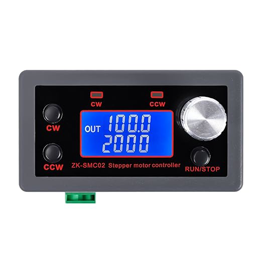
The ZK-SMC02 is a compact, high-performance motion controller designed for precise control of stepper and servo motors in automation applications. It is widely used in industrial automation, robotics, CNC machines, and other systems requiring accurate motor control. The ZK-SMC02 offers advanced features such as multi-axis control, programmable motion profiles, and compatibility with various communication protocols, making it a versatile choice for engineers and hobbyists alike.
Explore Projects Built with zk-smc02


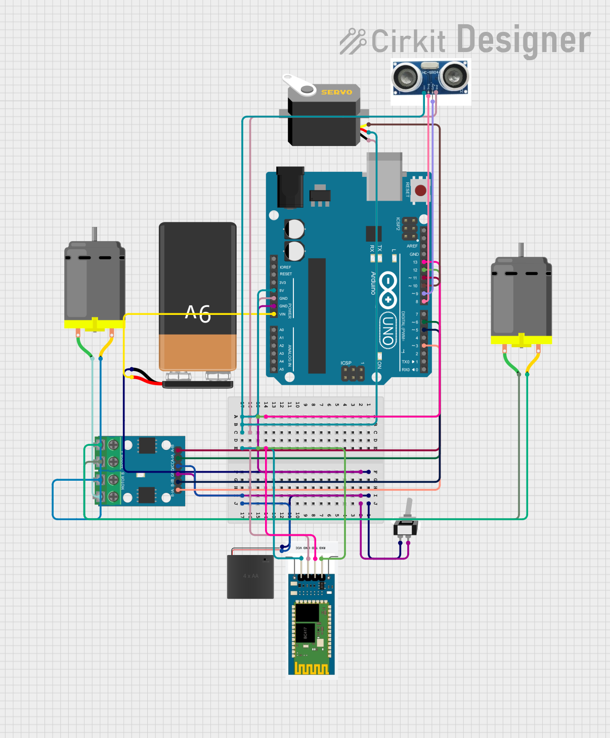

Explore Projects Built with zk-smc02
Common Applications
- CNC machines for precision cutting and milling
- Robotic arms for industrial automation
- Conveyor belt systems in manufacturing
- 3D printers for accurate layer deposition
- Automated testing equipment
Technical Specifications
Key Technical Details
| Parameter | Value |
|---|---|
| Input Voltage | 12V to 48V DC |
| Maximum Current Output | 5A per motor channel |
| Motor Compatibility | Stepper motors (2-phase, 3-phase), Servo motors |
| Communication Protocols | RS485, CAN, UART |
| Control Modes | Position, Velocity, Torque |
| Operating Temperature | -20°C to 60°C |
| Dimensions | 100mm x 60mm x 25mm |
Pin Configuration and Descriptions
Power and Motor Connections
| Pin Number | Name | Description |
|---|---|---|
| 1 | V+ | Positive DC power input (12V to 48V) |
| 2 | GND | Ground connection for power |
| 3 | A+ | Stepper motor phase A+ |
| 4 | A- | Stepper motor phase A- |
| 5 | B+ | Stepper motor phase B+ |
| 6 | B- | Stepper motor phase B- |
Communication and Control
| Pin Number | Name | Description |
|---|---|---|
| 7 | TX | Transmit data (UART/RS485) |
| 8 | RX | Receive data (UART/RS485) |
| 9 | CAN_H | CAN bus high |
| 10 | CAN_L | CAN bus low |
| 11 | EN | Enable signal for motor control |
| 12 | DIR | Direction control signal |
| 13 | PUL | Pulse signal for stepper motor |
Usage Instructions
How to Use the ZK-SMC02 in a Circuit
- Power Connection: Connect the V+ and GND pins to a DC power supply within the range of 12V to 48V.
- Motor Connection: Connect the stepper or servo motor wires to the corresponding A+, A-, B+, and B- pins.
- Control Signals: Use the EN, DIR, and PUL pins to control motor operation. These can be connected to a microcontroller or PLC.
- Communication: For advanced control, connect the TX and RX pins to a UART interface or use the CAN_H and CAN_L pins for CAN bus communication.
Important Considerations
- Ensure the power supply voltage matches the motor's requirements to avoid damage.
- Use proper heat dissipation methods, such as a heatsink or fan, if operating at high currents.
- Verify the motor's wiring to avoid incorrect connections that could damage the controller or motor.
- For stepper motors, configure the pulse frequency and direction signals appropriately for smooth operation.
Example: Connecting to an Arduino UNO
The ZK-SMC02 can be controlled using an Arduino UNO. Below is an example code snippet to control a stepper motor:
// Define control pins
#define EN_PIN 7    // Enable pin connected to Arduino digital pin 7
#define DIR_PIN 8   // Direction pin connected to Arduino digital pin 8
#define PUL_PIN 9   // Pulse pin connected to Arduino digital pin 9

void setup() {
  // Set pin modes
  pinMode(EN_PIN, OUTPUT);
  pinMode(DIR_PIN, OUTPUT);
  pinMode(PUL_PIN, OUTPUT);

  // Enable the motor controller
  digitalWrite(EN_PIN, LOW); // LOW to enable motor control
}

void loop() {
  // Set motor direction
  digitalWrite(DIR_PIN, HIGH); // HIGH for one direction, LOW for the other

  // Generate pulses to move the motor
  for (int i = 0; i < 200; i++) { // 200 pulses for one revolution (example)
    digitalWrite(PUL_PIN, HIGH);
    delayMicroseconds(500); // Adjust for motor speed
    digitalWrite(PUL_PIN, LOW);
    delayMicroseconds(500);
  }

  delay(1000); // Wait 1 second before reversing direction

  // Reverse direction
  digitalWrite(DIR_PIN, LOW);
  for (int i = 0; i < 200; i++) {
    digitalWrite(PUL_PIN, HIGH);
    delayMicroseconds(500);
    digitalWrite(PUL_PIN, LOW);
    delayMicroseconds(500);
  }

  delay(1000); // Wait 1 second before repeating
}
Best Practices
- Use shielded cables for communication lines to reduce noise interference.
- Implement proper grounding to avoid ground loops in the system.
- Regularly inspect connections and cables for wear or damage.
Troubleshooting and FAQs
Common Issues and Solutions
Motor Not Moving
- Cause: Incorrect wiring or loose connections.
- Solution: Double-check all motor and power connections. Ensure the EN pin is set to enable the motor.
Motor Vibrates but Does Not Rotate
- Cause: Incorrect pulse frequency or motor wiring.
- Solution: Verify the pulse signal timing and ensure the motor phases are connected correctly.
Overheating
- Cause: Excessive current or poor ventilation.
- Solution: Reduce the current limit or improve heat dissipation with a heatsink or fan.
Communication Failure
- Cause: Incorrect baud rate or wiring.
- Solution: Ensure the communication settings (e.g., baud rate) match between the controller and the host device. Check TX/RX or CAN bus connections.
FAQs
Can the ZK-SMC02 control multiple motors simultaneously? Yes, it supports multi-axis control for stepper and servo motors.
What is the maximum pulse frequency supported? The ZK-SMC02 supports pulse frequencies up to 200 kHz.
Is the ZK-SMC02 compatible with 3.3V logic microcontrollers? Yes, but you may need level shifters if the control signals require 5V logic.
Can I use the ZK-SMC02 with a battery-powered system? Yes, as long as the battery voltage is within the 12V to 48V range and can supply sufficient current.
By following this documentation, users can effectively integrate the ZK-SMC02 into their projects and troubleshoot common issues with ease.