How to Use GSM : Examples, Pinouts, and Specs
Introduction
GSM (Global System for Mobile Communications) is a standard developed to define protocols for second-generation (2G) digital cellular networks. It is widely used in mobile phones and other communication devices to enable voice and data transmission over cellular networks. GSM modules are commonly integrated into embedded systems to provide wireless communication capabilities.
Explore Projects Built with GSM
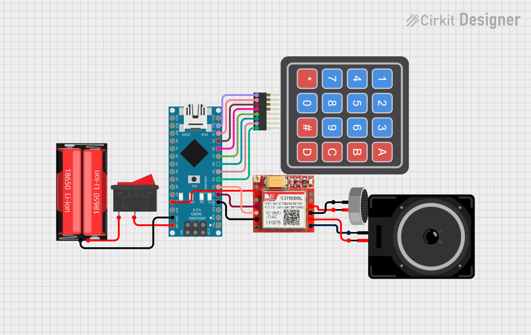
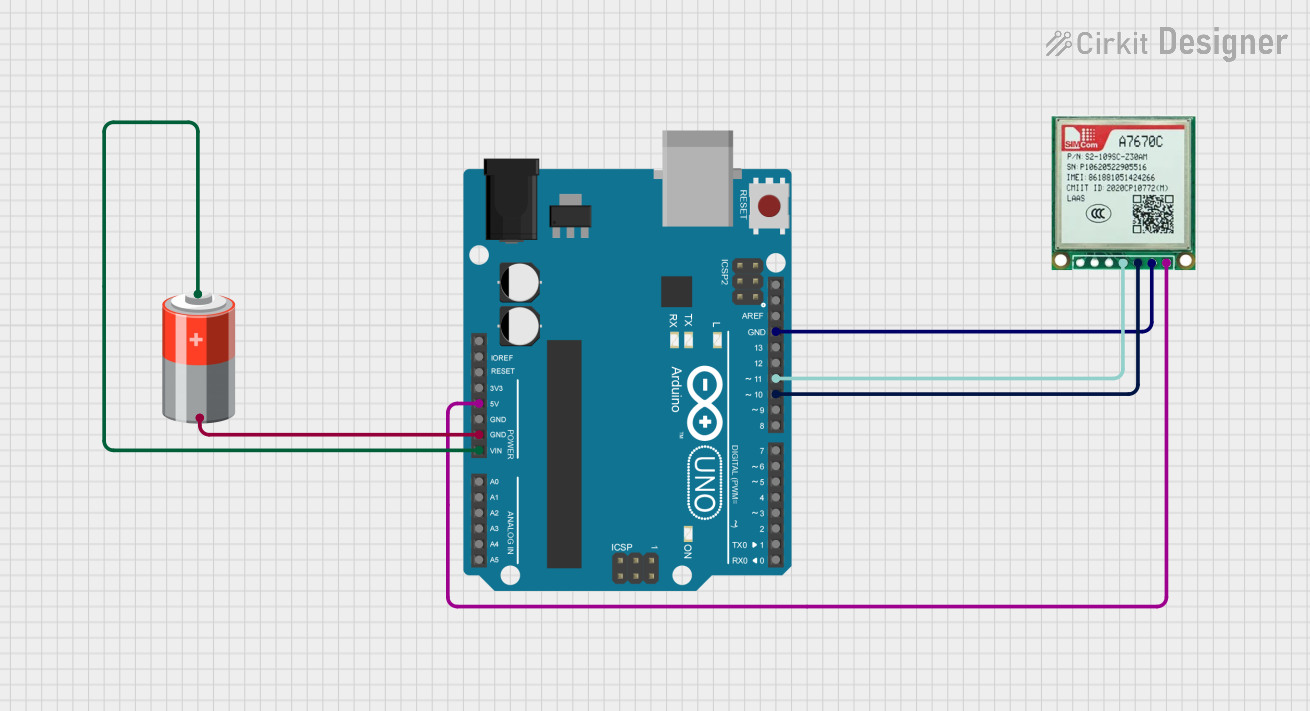
Explore Projects Built with GSM
Common Applications and Use Cases
- Mobile phones for voice and SMS communication
- IoT (Internet of Things) devices for remote monitoring and control
- GPS tracking systems
- Wireless data transmission in industrial automation
- Smart home devices for remote connectivity
Technical Specifications
Key Technical Details
- Frequency Bands: 850 MHz, 900 MHz, 1800 MHz, 1900 MHz (quad-band support)
- Supply Voltage: 3.4V to 4.4V (typical 4.0V)
- Power Consumption:
- Idle: ~10 mA
- Active (transmitting): ~200 mA to 2 A (depending on signal strength)
- Communication Protocols: AT commands over UART
- Data Rates: Up to 9.6 kbps for GPRS (General Packet Radio Service)
- SIM Card Support: 1.8V and 3V SIM cards
- Operating Temperature: -40°C to +85°C
Pin Configuration and Descriptions
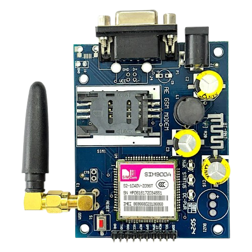
Below is a typical pinout for a GSM module (e.g., SIM800 or SIM900):
| Pin | Name | Description |
|---|---|---|
| 1 | VCC | Power supply input (3.4V to 4.4V). |
| 2 | GND | Ground connection. |
| 3 | TXD | Transmit data (UART output). |
| 4 | RXD | Receive data (UART input). |
| 5 | DTR | Data Terminal Ready (used for sleep mode control). |
| 6 | RST | Reset pin (active low). |
| 7 | NETLIGHT | Network status indicator (blinks to show GSM network activity). |
| 8 | SIM_VDD | Power supply for the SIM card. |
| 9 | SIM_DATA | Data line for SIM card communication. |
| 10 | SIM_CLK | Clock signal for SIM card communication. |
| 11 | SIM_RST | Reset signal for SIM card. |
| 12 | MIC+ | Microphone positive input (for voice communication). |
| 13 | MIC- | Microphone negative input (for voice communication). |
| 14 | SPK+ | Speaker positive output (for voice communication). |
| 15 | SPK- | Speaker negative output (for voice communication). |
Usage Instructions
How to Use the GSM Module in a Circuit
- Power Supply: Ensure the GSM module is powered with a stable voltage between 3.4V and 4.4V. Use a capacitor (e.g., 1000 µF) near the power pins to handle current surges during transmission.
- SIM Card: Insert a valid SIM card into the module's SIM card slot. Ensure the SIM card is activated and has sufficient balance for communication.
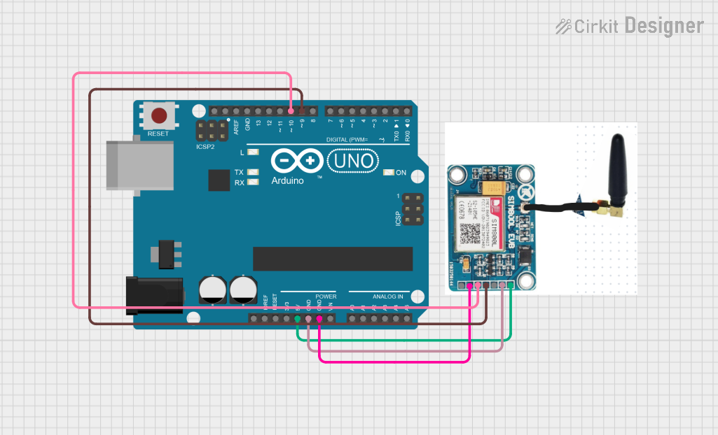
- UART Communication: Connect the TXD and RXD pins of the GSM module to the RX and TX pins of your microcontroller (e.g., Arduino UNO). Use a logic level converter if your microcontroller operates at 5V logic.
- Antenna: Attach an external antenna to the GSM module for better signal reception.
- AT Commands: Communicate with the GSM module using AT commands over UART to perform tasks such as sending SMS, making calls, or connecting to the internet.
Important Considerations and Best Practices
- Use a proper power supply to avoid voltage drops during high current consumption.
- Place the GSM module away from sensitive components to minimize electromagnetic interference.
- Ensure the antenna is securely connected for optimal signal strength.
- Use a baud rate of 9600 bps for UART communication unless otherwise specified in the module's datasheet.
- Always check the network status using the
AT+CREG?command before initiating communication.
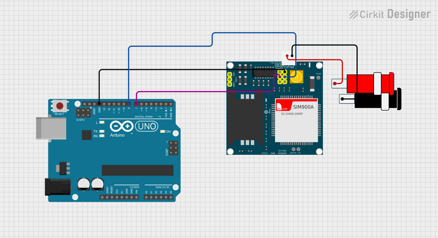
Example: Connecting GSM Module to Arduino UNO
Below is an example of how to send an SMS using an Arduino UNO and a GSM module:
#include <SoftwareSerial.h>

// Define RX and TX pins for SoftwareSerial
SoftwareSerial gsmSerial(7, 8); // RX = Pin 7, TX = Pin 8

void setup() {
  // Initialize serial communication
  Serial.begin(9600); // For debugging
  gsmSerial.begin(9600); // For GSM module communication

  Serial.println("Initializing GSM module...");
  delay(1000);

  // Send AT command to check communication
  gsmSerial.println("AT");
  delay(1000);

  // Set SMS text mode
  gsmSerial.println("AT+CMGF=1"); // Set SMS mode to text
  delay(1000);

  // Send SMS
  gsmSerial.println("AT+CMGS=\"+1234567890\""); // Replace with recipient's phone number
  delay(1000);
  gsmSerial.println("Hello, this is a test SMS from GSM module!"); // SMS content
  delay(1000);
  gsmSerial.write(26); // Send Ctrl+Z to indicate end of message
  delay(5000);

  Serial.println("SMS sent!");
}

void loop() {
  // No actions in loop
}
Notes:
- Replace
+1234567890with the recipient's phone number. - Ensure the GSM module is properly powered and connected to the Arduino.
Troubleshooting and FAQs
Common Issues and Solutions
GSM Module Not Responding to AT Commands:
- Cause: Incorrect baud rate or loose connections.
- Solution: Verify the baud rate (default is 9600 bps) and check all connections.
No Network Signal:
- Cause: Poor signal strength or missing antenna.
- Solution: Ensure the antenna is connected and positioned correctly. Check the SIM card's network coverage.
Module Restarts During Transmission:
- Cause: Insufficient power supply.
- Solution: Use a power supply capable of providing at least 2A current. Add a capacitor near the power pins.
Unable to Send SMS or Make Calls:
- Cause: SIM card not registered or insufficient balance.
- Solution: Check the SIM card status using the
AT+CREG?command and ensure it has sufficient balance.
Noise in Voice Communication:
- Cause: Poor grounding or interference.
- Solution: Improve grounding and keep the GSM module away from noise-sensitive components.
FAQs
Q: Can I use a 5V power supply for the GSM module?
A: No, the GSM module requires a voltage between 3.4V and 4.4V. Use a voltage regulator if needed.Q: How do I check the signal strength?
A: Use theAT+CSQcommand. The response will indicate the signal quality.Q: Can the GSM module connect to the internet?
A: Yes, GSM modules support GPRS for internet connectivity. Use AT commands likeAT+SAPBRto configure GPRS.Q: What is the typical range of a GSM module?
A: The range depends on the cellular network coverage, typically up to several kilometers in urban areas.
This documentation provides a comprehensive guide to using GSM modules effectively in your projects.