How to Use Elevation Motor Driver: Examples, Pinouts, and Specs
Introduction
The Elevation Motor Driver is a device designed to control the operation of motors used in elevating or lowering mechanisms. It provides precise control over motor direction and speed, making it ideal for applications requiring smooth and reliable motion. This component is commonly used in robotics, automated systems, conveyor belts, and other machinery where elevation control is critical.
Explore Projects Built with Elevation Motor Driver


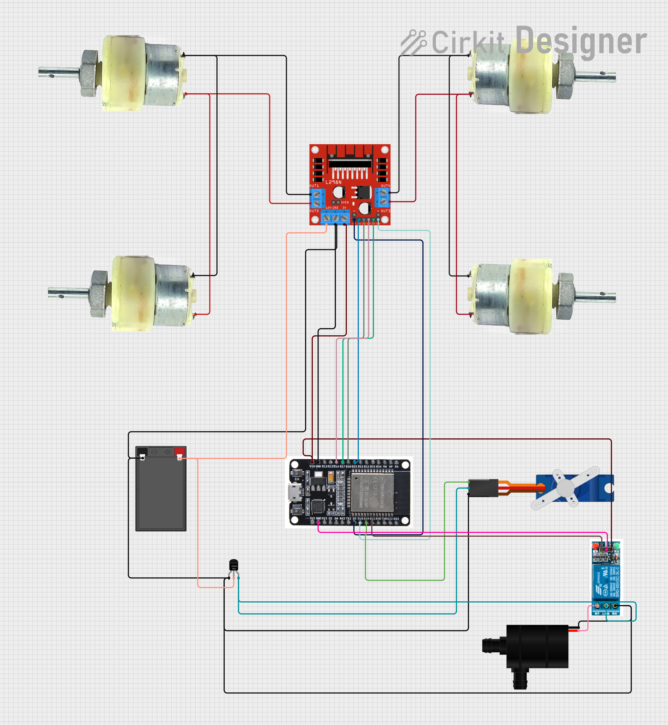
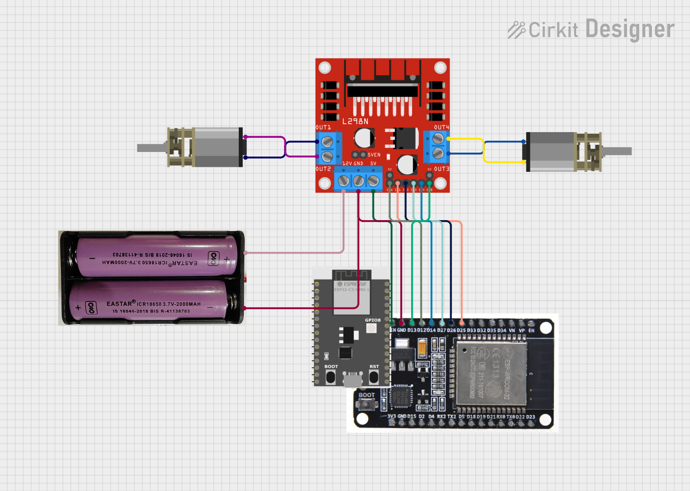
Explore Projects Built with Elevation Motor Driver
Common Applications and Use Cases
- Robotic arms for vertical movement
- Elevators and lifting platforms
- Adjustable conveyor systems
- Antenna positioning systems
- Automated storage and retrieval systems
Technical Specifications
The Elevation Motor Driver is designed to work with a wide range of DC motors and stepper motors. Below are the key technical details:
General Specifications
| Parameter | Value |
|---|---|
| Operating Voltage | 6V to 36V |
| Maximum Output Current | 2A per channel (continuous) |
| Peak Output Current | 3A per channel (short duration) |
| Control Logic Voltage | 3.3V or 5V (compatible with most microcontrollers) |
| PWM Frequency | Up to 20 kHz |
| Motor Channels | 2 (can control two motors independently) |
| Operating Temperature | -20°C to 85°C |
Pin Configuration and Descriptions
The Elevation Motor Driver typically comes with a 16-pin interface. Below is the pin configuration:
| Pin Number | Pin Name | Description |
|---|---|---|
| 1 | VCC | Power supply for the motor driver (6V to 36V). |
| 2 | GND | Ground connection. |
| 3 | IN1 | Input signal for controlling Motor 1 direction. |
| 4 | IN2 | Input signal for controlling Motor 1 direction. |
| 5 | ENA | PWM input for controlling Motor 1 speed. |
| 6 | IN3 | Input signal for controlling Motor 2 direction. |
| 7 | IN4 | Input signal for controlling Motor 2 direction. |
| 8 | ENB | PWM input for controlling Motor 2 speed. |
| 9 | OUT1 | Output terminal for Motor 1. |
| 10 | OUT2 | Output terminal for Motor 1. |
| 11 | OUT3 | Output terminal for Motor 2. |
| 12 | OUT4 | Output terminal for Motor 2. |
| 13 | 5V | Logic voltage input (3.3V or 5V). |
| 14 | NC | Not connected. |
| 15 | Fault | Fault indicator pin (active low). |
| 16 | Standby | Standby mode control (active low). |
Usage Instructions
How to Use the Component in a Circuit
- Power Supply: Connect the VCC pin to a power source within the operating voltage range (6V to 36V). Connect the GND pin to the ground of the power source.
- Motor Connections: Connect the motor terminals to the OUT1, OUT2 (for Motor 1) and OUT3, OUT4 (for Motor 2) pins.
- Control Signals: Use the IN1, IN2, and ENA pins to control the direction and speed of Motor 1. Similarly, use IN3, IN4, and ENB for Motor 2.
- Logic Voltage: Provide a 3.3V or 5V logic voltage to the 5V pin to ensure compatibility with your microcontroller.
- PWM Control: Use PWM signals on the ENA and ENB pins to control motor speed. A higher duty cycle corresponds to a higher speed.
Important Considerations and Best Practices
- Ensure the power supply voltage matches the motor's operating voltage to avoid damage.
- Use appropriate heat sinks or cooling mechanisms if operating near the maximum current rating.
- Avoid reversing the polarity of the power supply or motor connections.
- Use decoupling capacitors near the VCC and GND pins to reduce noise and improve stability.
- If using with an Arduino UNO, ensure the PWM pins used for ENA and ENB are capable of generating PWM signals.
Example Code for Arduino UNO
Below is an example code snippet to control a motor using the Elevation Motor Driver and an Arduino UNO:
// Define motor control pins
const int IN1 = 7;  // Motor 1 direction control pin
const int IN2 = 8;  // Motor 1 direction control pin
const int ENA = 9;  // Motor 1 speed control (PWM pin)

void setup() {
  // Set motor control pins as outputs
  pinMode(IN1, OUTPUT);
  pinMode(IN2, OUTPUT);
  pinMode(ENA, OUTPUT);
}

void loop() {
  // Rotate motor in one direction
  digitalWrite(IN1, HIGH);  // Set IN1 high
  digitalWrite(IN2, LOW);   // Set IN2 low
  analogWrite(ENA, 128);    // Set speed to 50% (PWM value: 128 out of 255)
  delay(2000);              // Run for 2 seconds

  // Stop the motor
  analogWrite(ENA, 0);      // Set speed to 0
  delay(1000);              // Wait for 1 second

  // Rotate motor in the opposite direction
  digitalWrite(IN1, LOW);   // Set IN1 low
  digitalWrite(IN2, HIGH);  // Set IN2 high
  analogWrite(ENA, 200);    // Set speed to ~78% (PWM value: 200 out of 255)
  delay(2000);              // Run for 2 seconds

  // Stop the motor
  analogWrite(ENA, 0);      // Set speed to 0
  delay(1000);              // Wait for 1 second
}
Troubleshooting and FAQs
Common Issues and Solutions
Motor Not Running:
- Ensure the power supply is connected and within the specified voltage range.
- Verify that the control signals (IN1, IN2, ENA) are correctly configured.
- Check motor connections to the output pins (OUT1, OUT2, etc.).
Motor Running in the Wrong Direction:
- Swap the IN1 and IN2 signals (or IN3 and IN4 for Motor 2) to reverse the direction.
Overheating:
- Ensure the current drawn by the motor does not exceed the driver's maximum rating.
- Use a heat sink or cooling fan if necessary.
PWM Signal Not Working:
- Confirm that the ENA and ENB pins are connected to PWM-capable pins on the microcontroller.
- Check the PWM frequency and ensure it is within the driver's supported range.
FAQs
Q: Can I use this driver with a stepper motor?
A: Yes, the Elevation Motor Driver can control stepper motors, but you will need to configure the control signals appropriately for stepper motor operation.
Q: What happens if I exceed the maximum current rating?
A: Exceeding the current rating may trigger the driver's protection mechanisms or cause permanent damage. Always ensure the motor's current requirements are within the driver's limits.
Q: Is this driver compatible with Raspberry Pi?
A: Yes, the driver is compatible with Raspberry Pi, but you may need a logic level shifter if the Raspberry Pi's GPIO voltage (3.3V) is not sufficient for the driver's logic inputs.
Q: Can I control two motors independently?
A: Yes, the driver supports independent control of two motors using separate control pins (IN1, IN2, ENA for Motor 1 and IN3, IN4, ENB for Motor 2).