How to Use pressure gage : Examples, Pinouts, and Specs
Introduction
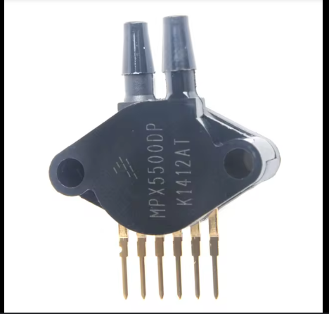
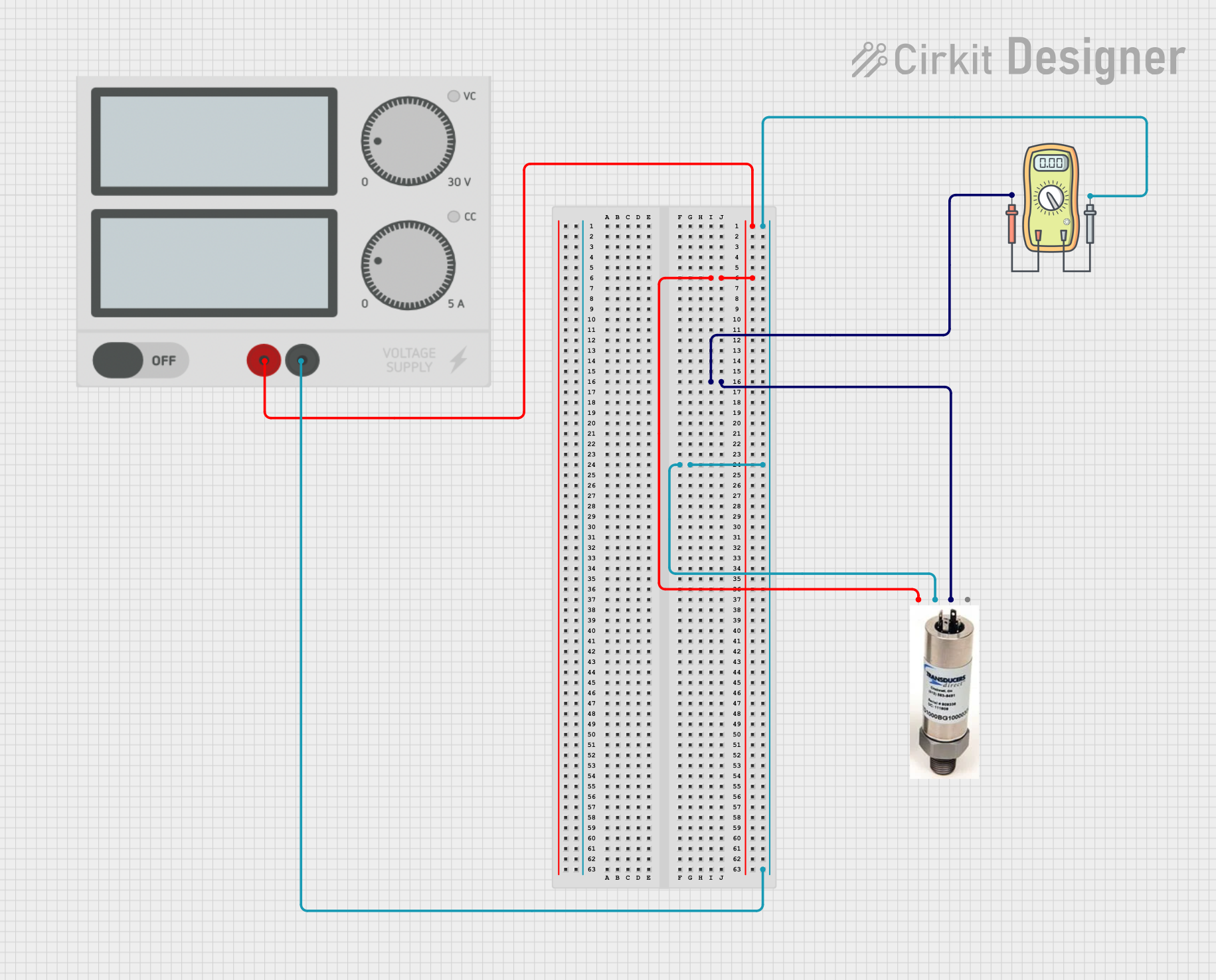
The Pressure Gage (Manufacturer Part ID: gage) is a device designed to measure the pressure of gases or liquids within a system. This component is essential in various applications, including industrial processes, automotive systems, HVAC systems, and laboratory experiments. By providing accurate pressure readings, the Pressure Gage helps ensure the safety, efficiency, and reliability of systems that rely on precise pressure control.
Explore Projects Built with pressure gage
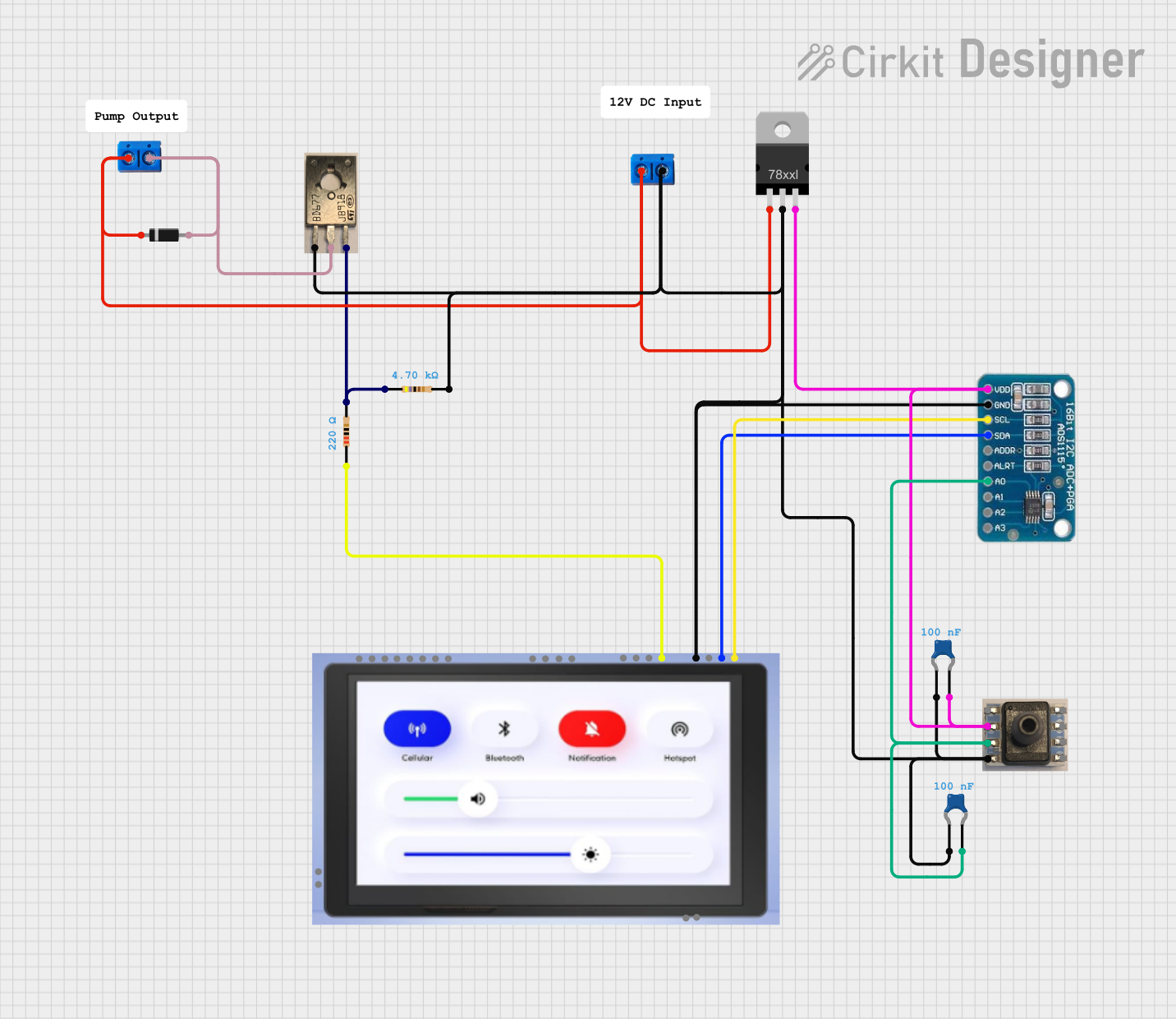
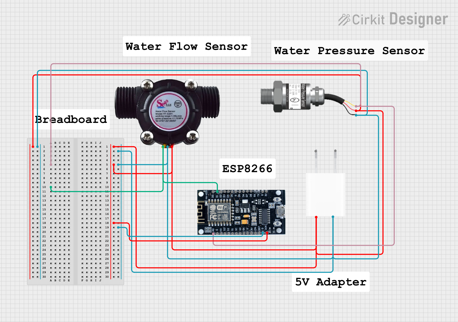
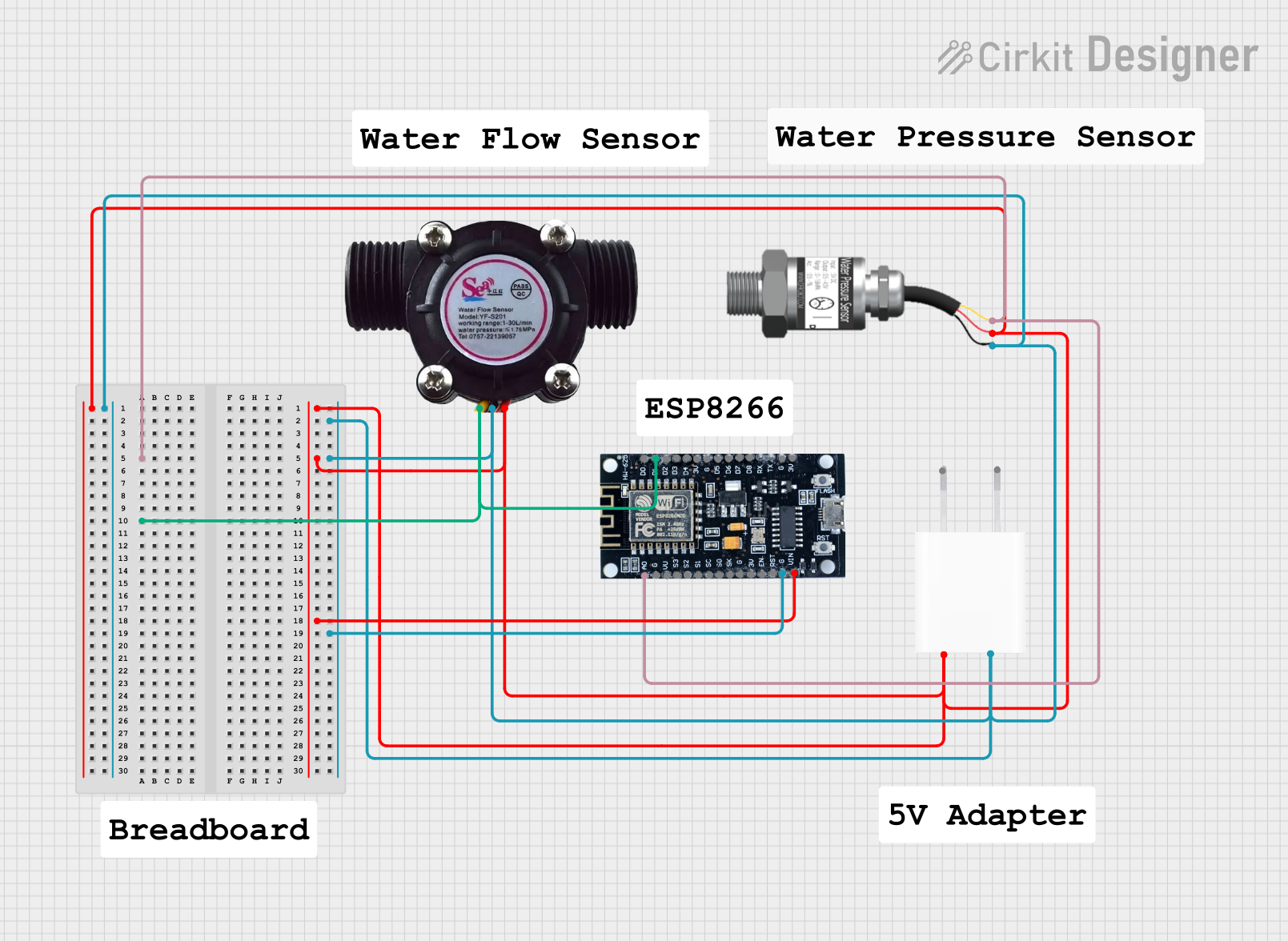
Explore Projects Built with pressure gage
Technical Specifications
Key Technical Details
| Parameter | Value |
|---|---|
| Manufacturer | pressure |
| Part ID | gage |
| Pressure Range | 0 to 100 PSI |
| Accuracy | ±1% of full scale |
| Operating Voltage | 5V DC |
| Output Signal | Analog (0.5V to 4.5V) |
| Operating Temperature | -20°C to 85°C |
| Response Time | < 10 ms |
| Connection Type | 1/4" NPT |
Pin Configuration and Descriptions
| Pin Number | Pin Name | Description |
|---|---|---|
| 1 | VCC | Power supply (5V DC) |
| 2 | GND | Ground |
| 3 | OUT | Analog output signal (0.5V to 4.5V) |
Usage Instructions
How to Use the Component in a Circuit
- Power Supply: Connect the VCC pin to a 5V DC power supply.
- Ground: Connect the GND pin to the ground of the power supply.
- Output Signal: Connect the OUT pin to an analog input pin of a microcontroller (e.g., Arduino UNO).
Important Considerations and Best Practices
- Calibration: Ensure the Pressure Gage is calibrated before use to maintain accuracy.
- Temperature: Operate within the specified temperature range to avoid damage.
- Mounting: Securely mount the gage to prevent vibrations and mechanical stress.
- Wiring: Use proper wiring techniques to avoid electrical noise and signal interference.
Example Circuit with Arduino UNO
// Example code to read pressure values from the Pressure Gage
// and display them on the Serial Monitor

const int pressurePin = A0; // Analog pin connected to OUT pin of Pressure Gage

void setup() {
  Serial.begin(9600); // Initialize serial communication at 9600 baud rate
}

void loop() {
  int sensorValue = analogRead(pressurePin); // Read the analog value from the sensor
  float voltage = sensorValue * (5.0 / 1023.0); // Convert the analog value to voltage
  float pressure = (voltage - 0.5) * (100.0 / 4.0); // Convert voltage to pressure (PSI)

  Serial.print("Pressure: ");
  Serial.print(pressure);
  Serial.println(" PSI");

  delay(1000); // Wait for 1 second before taking another reading
}
Troubleshooting and FAQs
Common Issues Users Might Face
Inaccurate Readings:
- Solution: Ensure the gage is properly calibrated and check for any leaks in the system.
No Output Signal:
- Solution: Verify the power supply connections and ensure the gage is receiving 5V DC.
Fluctuating Readings:
- Solution: Check for electrical noise and ensure proper grounding. Use shielded cables if necessary.
FAQs
Q1: Can the Pressure Gage be used with liquids and gases?
- A1: Yes, the Pressure Gage is designed to measure the pressure of both gases and liquids.
Q2: What is the response time of the Pressure Gage?
- A2: The response time is less than 10 milliseconds.
Q3: How do I calibrate the Pressure Gage?
- A3: Calibration procedures vary by model. Refer to the manufacturer's calibration guide for detailed instructions.
Q4: Can I use the Pressure Gage with a 3.3V microcontroller?
- A4: The Pressure Gage requires a 5V DC power supply. Use a level shifter to interface with a 3.3V microcontroller.
By following this documentation, users can effectively integrate the Pressure Gage into their systems, ensuring accurate and reliable pressure measurements.