How to Use KF-301 Relay: Examples, Pinouts, and Specs
Introduction
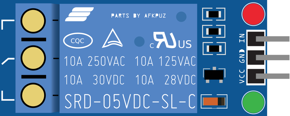
The KF-301 Relay is an electromagnetic switch module widely used in electronics for controlling high power devices and circuits using low power signals. It is particularly useful in situations where you need to control AC or DC loads with a microcontroller like an Arduino UNO. Common applications include home automation, industrial controls, and switching devices on and off remotely.
Explore Projects Built with KF-301 Relay
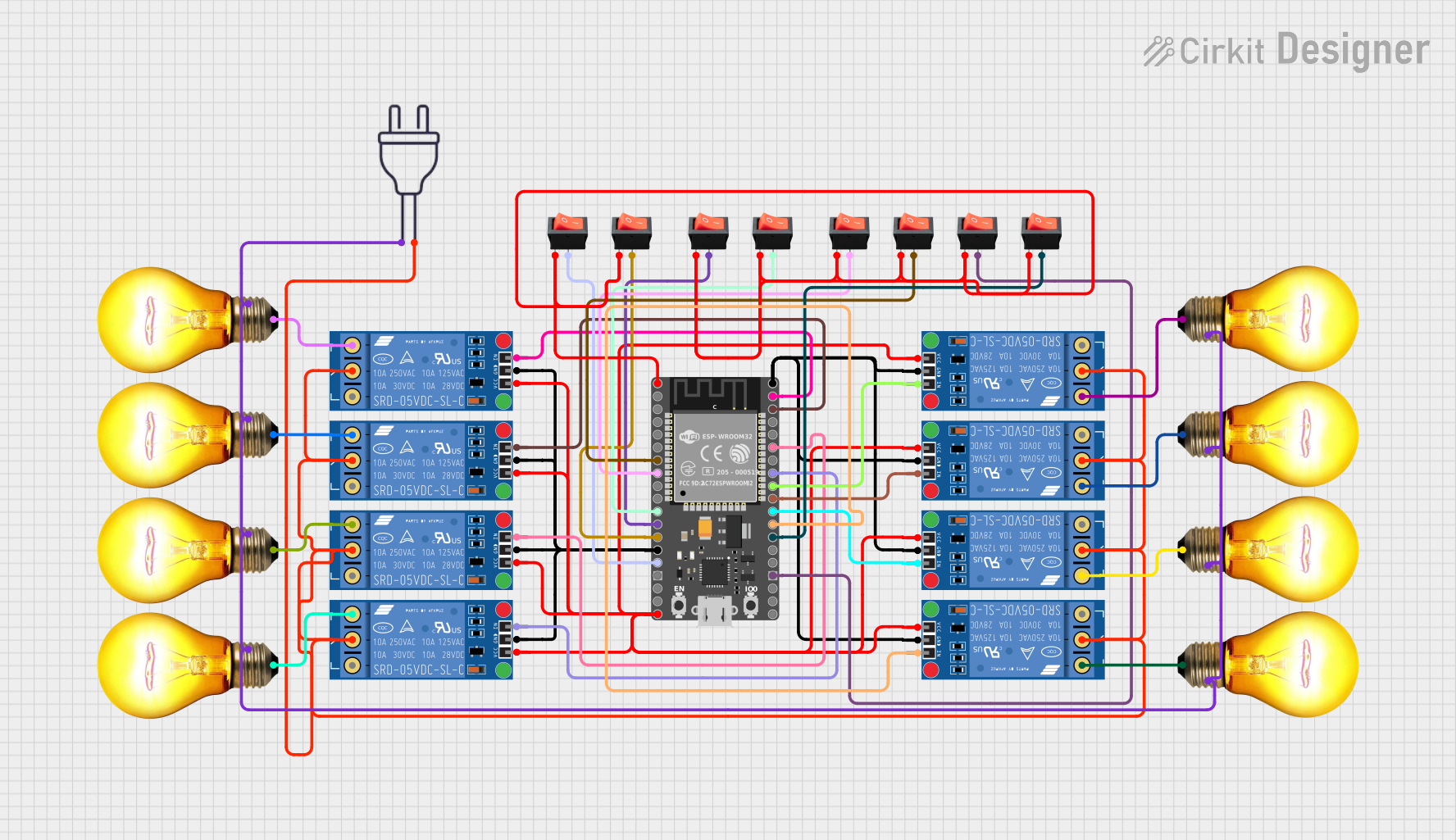
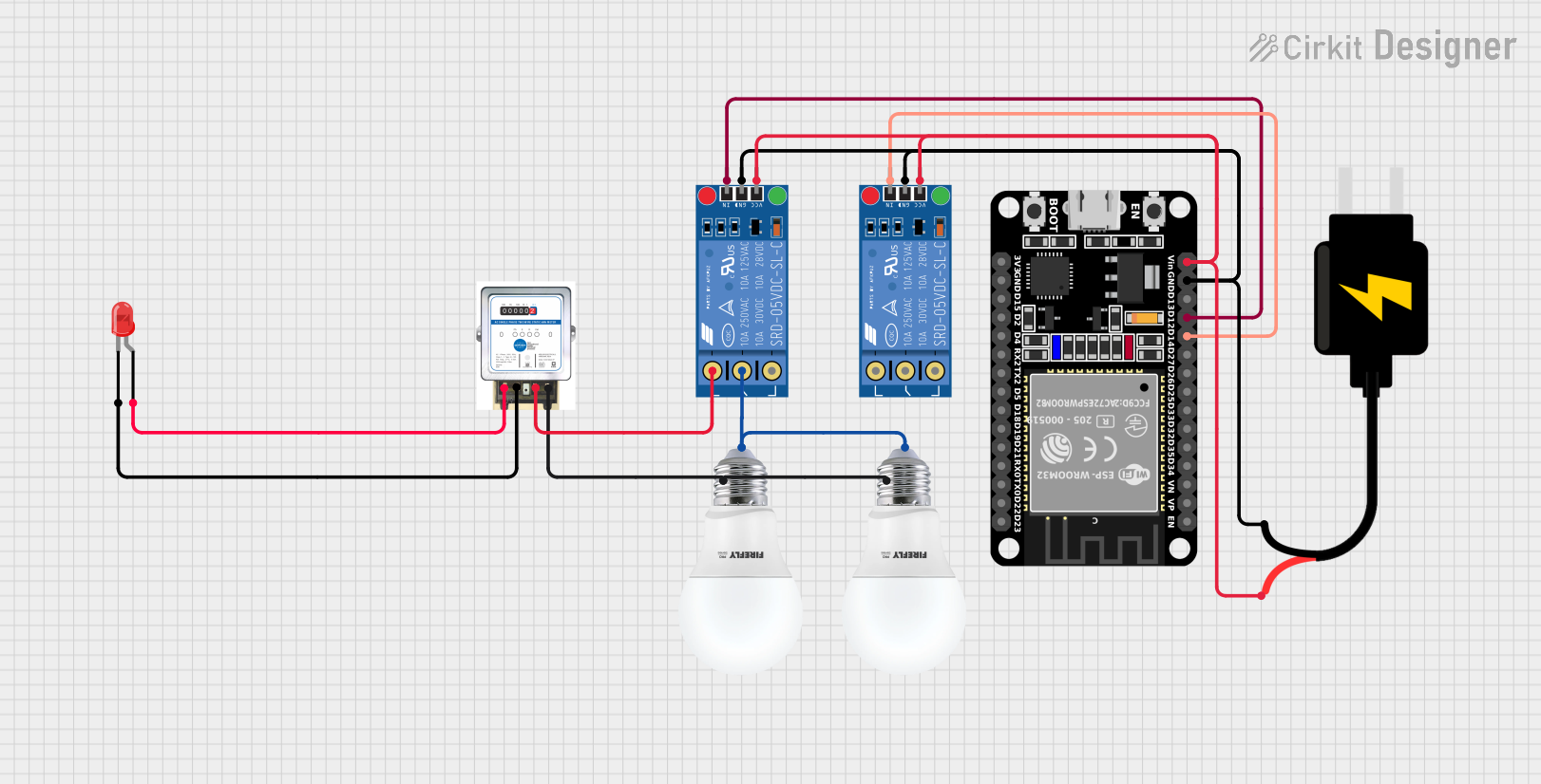
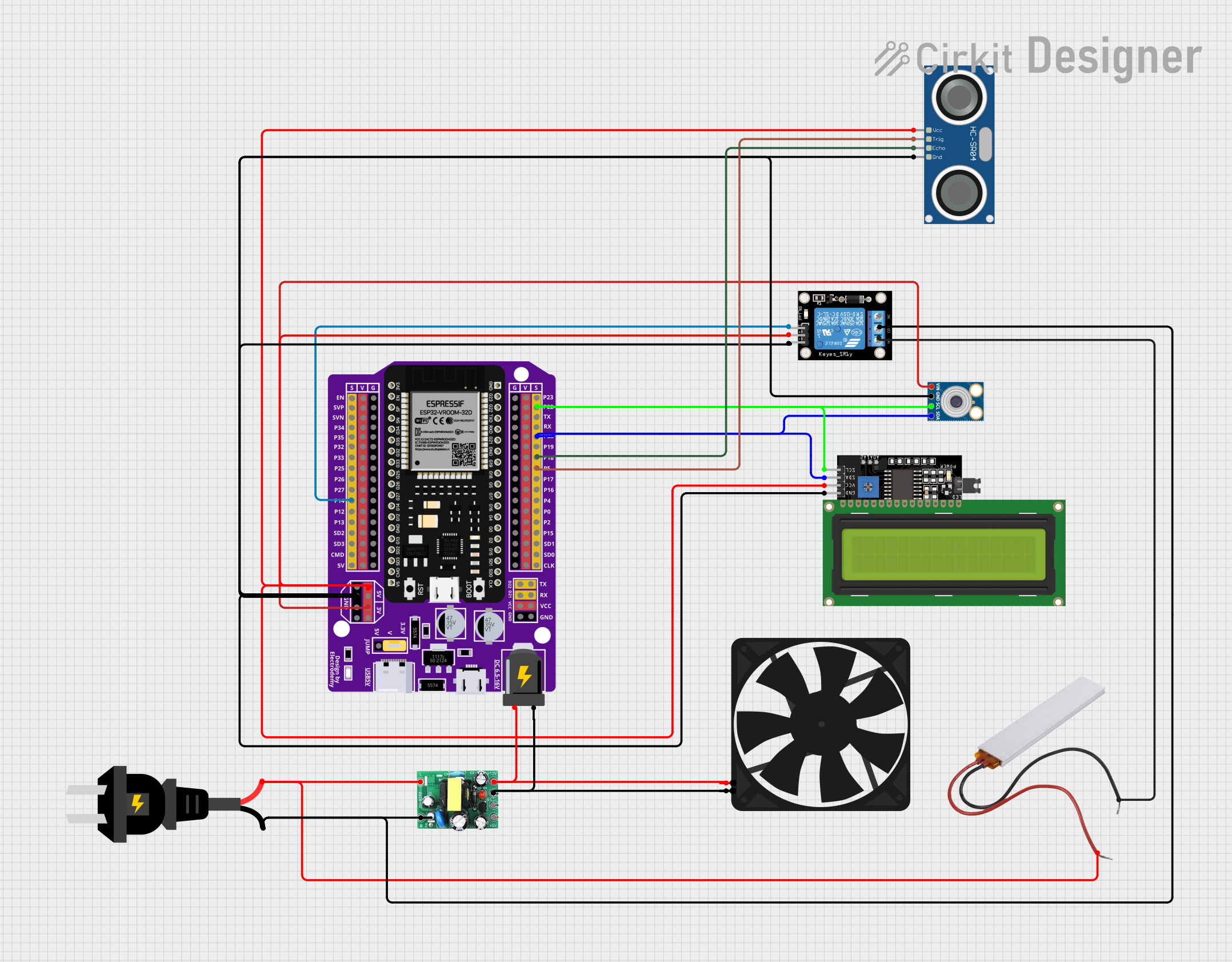
Explore Projects Built with KF-301 Relay
Technical Specifications
Key Technical Details
- Operating Voltage (Coil): 5V DC
- Current Rating: 10A at 250V AC or 10A at 30V DC
- Switching Voltage: Up to 250V AC or 30V DC
- Switching Capacity: Up to 2500VA or 300W
- Operating Time: 10ms Release Time
- Release Time: 5ms
- Life Expectancy (Mechanical): 10,000,000 operations
- Life Expectancy (Electrical): 100,000 operations
Pin Configuration and Descriptions
| Pin Number | Description | Notes |
|---|---|---|
| 1 | Normally Open (NO) | Contact closes when coil is energized |
| 2 | Common (COM) | Connects to NO or NC depending on coil state |
| 3 | Normally Closed (NC) | Contact opens when coil is energized |
| 4 | Coil+ (VCC) | Connect to 5V supply |
| 5 | Coil- (GND) | Connect to ground |
| 6 | Input Signal (IN) | Trigger signal from microcontroller |
Usage Instructions
Connecting the KF-301 Relay to a Circuit
- Connect the Coil+ (VCC) pin to a 5V power supply.
- Connect the Coil- (GND) pin to the ground of the power supply.
- Connect the Input Signal (IN) pin to a digital output pin of a microcontroller.
- Connect the Common (COM) pin to the power line of the load you wish to control.
- Connect the Normally Open (NO) pin to the device you want to control. Use Normally Closed (NC) if you want the device to be powered until the relay is activated.
Important Considerations and Best Practices
- Ensure the load does not exceed the relay's maximum voltage and current ratings.
- Use a flyback diode across the relay coil to prevent back EMF when the coil is de-energized.
- Consider using a snubber circuit for inductive loads to prevent voltage spikes.
- Always ensure proper isolation between the low voltage control side and high voltage load side.
Example Code for Arduino UNO
// Define the relay control pin
#define RELAY_PIN 7

void setup() {
  // Set the relay control pin as an output
  pinMode(RELAY_PIN, OUTPUT);
}

void loop() {
  // Turn on the relay by setting the control pin HIGH
  digitalWrite(RELAY_PIN, HIGH);
  delay(1000); // Wait for 1 second

  // Turn off the relay by setting the control pin LOW
  digitalWrite(RELAY_PIN, LOW);
  delay(1000); // Wait for 1 second
}
Troubleshooting and FAQs
Common Issues
- Relay does not switch: Check the input signal and power connections. Ensure the control signal is reaching the relay's input.
- Intermittent operation: Verify that the contacts are not worn out and that the coil voltage is stable.
- Clicking sound but no action: This could indicate a problem with the contacts or insufficient power to the coil.
Solutions and Tips
- Ensure stable connections: Loose connections can cause intermittent operation or failure to actuate.
- Check the input signal: Use a multimeter to verify that the control signal is within the expected range.
- Replace if necessary: If the relay has reached its end of life due to extensive use, consider replacing it.
FAQs
Q: Can I control the KF-301 Relay with a 3.3V signal? A: The relay requires a 5V signal to reliably actuate. Use a level shifter if you're controlling it with a 3.3V microcontroller.
Q: Is it safe to switch AC loads with the KF-301 Relay? A: Yes, but ensure you have proper knowledge of working with high voltage and take necessary safety precautions.
Q: How can I extend the life of the relay? A: Minimize the load on the contacts, use snubber circuits for inductive loads, and avoid frequent switching if possible.