How to Use 24x18 Pin PCB Board: Examples, Pinouts, and Specs
Introduction
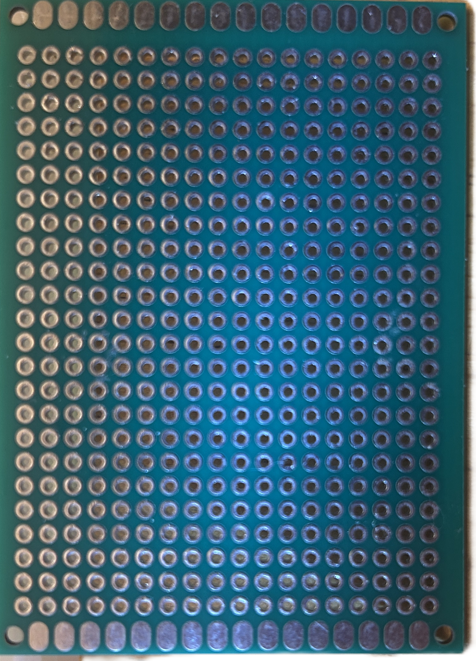
The 24x18 Pin PCB Board is a versatile printed circuit board designed for prototyping and connecting electronic components. With 24 rows and 18 columns of pins, this board provides ample space for creating and testing custom circuits. It is ideal for hobbyists, students, and professionals working on small to medium-sized electronic projects.
Explore Projects Built with 24x18 Pin PCB Board


Explore Projects Built with 24x18 Pin PCB Board
Common Applications and Use Cases
- Prototyping and testing electronic circuits
- Building custom circuit designs for microcontrollers
- Creating breakout boards for sensors and modules
- Educational projects and learning circuit design
- Repairing or modifying existing circuits
Technical Specifications
The 24x18 Pin PCB Board is designed to be user-friendly and compatible with a wide range of electronic components. Below are the key technical details:
General Specifications
| Parameter | Value |
|---|---|
| Dimensions | 24 rows x 18 columns |
| Material | FR4 (Flame Retardant 4) |
| Thickness | 1.6 mm |
| Copper Layer Thickness | 35 µm (1 oz/ft²) |
| Hole Diameter | 1.0 mm |
| Pin Pitch | 2.54 mm (standard spacing) |
| Surface Finish | HASL (Hot Air Solder Leveling) |
| Solder Mask Color | Green |
Pin Configuration and Descriptions
The board features a grid of through-hole pins arranged in a 24x18 matrix. Each pin is plated and spaced at a standard 2.54 mm pitch, making it compatible with most through-hole components and headers.
| Pin Type | Description |
|---|---|
| Through-hole | Standard plated holes for soldering components or connecting wires |
| Power Rails | Dedicated rows for power (VCC) and ground (GND) connections (if applicable) |
| Signal Pins | General-purpose pins for connecting resistors, capacitors, ICs, etc. |
Usage Instructions
The 24x18 Pin PCB Board is straightforward to use and can be adapted for various circuit designs. Follow the steps below to get started:
How to Use the Component in a Circuit
- Plan Your Circuit Design: Sketch your circuit on paper or use PCB design software to map out the connections.
- Place Components: Insert components such as resistors, capacitors, ICs, and connectors into the through-hole pins.
- Solder Connections: Use a soldering iron and solder to secure the components to the board. Ensure clean and strong solder joints.
- Route Wires: Use jumper wires or solder traces to connect the pins according to your circuit design.
- Test the Circuit: Before powering the circuit, double-check all connections for errors or shorts. Then, test the circuit with a power supply.
Important Considerations and Best Practices
- Avoid Overheating: Excessive heat during soldering can damage the PCB or components. Use a temperature-controlled soldering iron.
- Use Flux: Apply flux to improve solder flow and ensure reliable connections.
- Label Connections: Use a marker or labels to identify key pins (e.g., VCC, GND) for easier debugging.
- Clean the Board: After soldering, clean the board with isopropyl alcohol to remove flux residue.
- Use Standoffs: If mounting the PCB in an enclosure, use standoffs to prevent short circuits.
Example: Connecting to an Arduino UNO
The 24x18 Pin PCB Board can be used to create a custom shield for an Arduino UNO. Below is an example of connecting an LED and a resistor to an Arduino using the PCB:
Circuit Diagram
- Connect the LED's anode to a digital pin (e.g., D13) via a 220-ohm resistor.
- Connect the LED's cathode to GND.
Arduino Code
// Simple LED Blink Example
// This code blinks an LED connected to pin 13 on the Arduino UNO.

const int ledPin = 13; // Define the pin connected to the LED

void setup() {
  pinMode(ledPin, OUTPUT); // Set the LED pin as an output
}

void loop() {
  digitalWrite(ledPin, HIGH); // Turn the LED on
  delay(1000);               // Wait for 1 second
  digitalWrite(ledPin, LOW);  // Turn the LED off
  delay(1000);               // Wait for 1 second
}
Troubleshooting and FAQs
Common Issues Users Might Face
Cold Solder Joints: Poor soldering can result in unreliable connections.
- Solution: Reheat the joint and apply a small amount of solder to ensure a solid connection.
Short Circuits: Adjacent pins may accidentally be bridged with solder.
- Solution: Use a solder wick or desoldering pump to remove excess solder.
Component Misplacement: Components may be inserted into the wrong pins.
- Solution: Double-check the circuit design and ensure components are placed correctly.
Damaged Traces: Excessive heat or force can damage the copper traces.
- Solution: Use a thin wire to repair broken connections.
FAQs
Q: Can I use this PCB for surface-mount components?
A: This board is designed for through-hole components. However, you can manually solder surface-mount components if needed, using jumper wires for connections.
Q: Is the board reusable?
A: Yes, the board can be reused if components are carefully desoldered. However, repeated soldering and desoldering may degrade the board's quality.
Q: What tools do I need to work with this PCB?
A: You will need a soldering iron, solder, flux, wire cutters, and optionally a multimeter for testing.
By following this documentation, you can effectively use the 24x18 Pin PCB Board for your electronic projects. Happy prototyping!