How to Use Micro PD Board: Examples, Pinouts, and Specs
Introduction
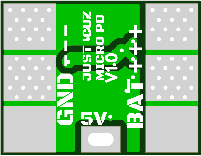
The Micro PD Board is a compact and versatile power delivery (PD) board designed to manage power distribution and charging for a wide range of devices. It is commonly equipped with USB-C connectivity and supports multiple power profiles, making it ideal for modern electronics that require efficient and flexible power management. The board is widely used in applications such as portable device charging, power banks, embedded systems, and prototyping projects.
Explore Projects Built with Micro PD Board


Explore Projects Built with Micro PD Board
Common Applications
- Charging portable devices (e.g., smartphones, tablets, and laptops)
- Powering embedded systems and IoT devices
- Prototyping USB-C power delivery circuits
- Power management in custom electronics projects
Technical Specifications
The Micro PD Board is designed to comply with USB Power Delivery (USB-PD) standards, offering a range of power profiles to suit various devices. Below are the key technical specifications:
| Parameter | Specification |
|---|---|
| Input Voltage Range | 5V to 20V (via USB-C port) |
| Output Voltage Profiles | 5V, 9V, 12V, 15V, 20V (selectable) |
| Maximum Output Current | 3A (depending on the selected profile) |
| Power Output | Up to 60W |
| Connector Type | USB-C (input/output) |
| Communication Protocol | USB Power Delivery (PD 3.0 compliant) |
| Dimensions | Compact (e.g., 25mm x 30mm, varies by model) |
| Protection Features | Overcurrent, overvoltage, and thermal protection |
Pin Configuration and Descriptions
The Micro PD Board typically features a USB-C connector and additional pins for integration into custom circuits. Below is a description of the key pins:
| Pin Name | Description |
|---|---|
| VBUS | Main power output (voltage depends on selected profile) |
| GND | Ground connection |
| CC1, CC2 | Configuration channel pins for USB-PD communication |
| SCL | I2C clock line (optional, for advanced configurations) |
| SDA | I2C data line (optional, for advanced configurations) |
| EN | Enable pin to activate or deactivate the board |
| SEL1, SEL2 | Voltage profile selection pins (logic-controlled) |
Usage Instructions
How to Use the Micro PD Board in a Circuit
Connect the Input Power Source:
Plug a USB-C power adapter into the board's USB-C port. Ensure the adapter supports the desired power profile (e.g., 5V, 9V, 12V, etc.).Select the Output Voltage Profile:
Use the SEL1 and SEL2 pins to configure the desired output voltage. Refer to the table below for the selection logic:SEL1 SEL2 Output Voltage Low Low 5V Low High 9V High Low 12V High High 20V Connect the Load:
Attach the device or circuit to the VBUS and GND pins. Ensure the load does not exceed the maximum current rating of 3A.Enable the Board:
Pull the EN pin high to activate the board. If the EN pin is left floating or pulled low, the board will remain disabled.Monitor Operation:
Use an optional I2C interface (SCL and SDA pins) to monitor power delivery status or configure advanced settings.
Important Considerations
- Always verify the power requirements of your load before connecting it to the Micro PD Board.
- Use appropriate heat dissipation methods if operating at high power levels for extended periods.
- Ensure the USB-C power adapter is compliant with USB-PD standards to avoid compatibility issues.
- Avoid shorting the VBUS and GND pins, as this may damage the board or the power source.
Example: Using the Micro PD Board with an Arduino UNO
The Micro PD Board can be integrated with an Arduino UNO for advanced control and monitoring. Below is an example code snippet to configure the board via I2C:
#include <Wire.h> // Include the Wire library for I2C communication

#define MICRO_PD_ADDR 0x28 // Replace with the actual I2C address of the board

void setup() {
  Wire.begin(); // Initialize I2C communication
  Serial.begin(9600); // Start serial communication for debugging

  // Example: Set the board to 12V output using I2C
  Wire.beginTransmission(MICRO_PD_ADDR);
  Wire.write(0x01); // Command to set voltage profile
  Wire.write(0x02); // Profile ID for 12V (refer to board documentation)
  Wire.endTransmission();

  Serial.println("Micro PD Board configured to 12V output.");
}

void loop() {
  // Monitor the board status (optional)
  Wire.requestFrom(MICRO_PD_ADDR, 1); // Request 1 byte of status data
  if (Wire.available()) {
    byte status = Wire.read();
    Serial.print("Board Status: ");
    Serial.println(status, HEX);
  }
  delay(1000); // Wait 1 second before the next status check
}
Notes:
- Replace
MICRO_PD_ADDRwith the actual I2C address of your Micro PD Board. - Refer to the board's datasheet for additional I2C commands and status codes.
Troubleshooting and FAQs
Common Issues and Solutions
Board Does Not Power On:
- Ensure the USB-C power adapter is properly connected and functional.
- Verify that the EN pin is pulled high to enable the board.
Incorrect Output Voltage:
- Check the SEL1 and SEL2 pin configurations to ensure the correct voltage profile is selected.
- Confirm that the power adapter supports the desired voltage profile.
Overheating:
- Ensure the load does not exceed the maximum power rating of the board.
- Use a heatsink or active cooling if operating at high power levels.
I2C Communication Fails:
- Verify the I2C address of the board and ensure it matches the code.
- Check the connections to the SCL and SDA pins for proper wiring.
FAQs
Q: Can the Micro PD Board be used with non-USB-C power sources?
A: No, the board is designed specifically for USB-C power delivery and requires a compliant USB-C power adapter.
Q: How do I reset the board to its default settings?
A: Disconnect the power source and ensure all configuration pins (SEL1, SEL2, EN) are set to their default states (low).
Q: Is the board compatible with Quick Charge (QC) devices?
A: The Micro PD Board is designed for USB-PD standards and may not be compatible with QC-specific protocols.
By following this documentation, users can effectively integrate the Micro PD Board into their projects and troubleshoot common issues with ease.