Cirkit Designer Logo
Cirkit Designer
Your all-in-one circuit design IDE
Home / 
Component Documentation

How to Use Modbus 4CH I/O: Examples, Pinouts, and Specs

Image of Modbus 4CH I/O
Cirkit Designer LogoDesign with Modbus 4CH I/O in Cirkit Designer

Introduction

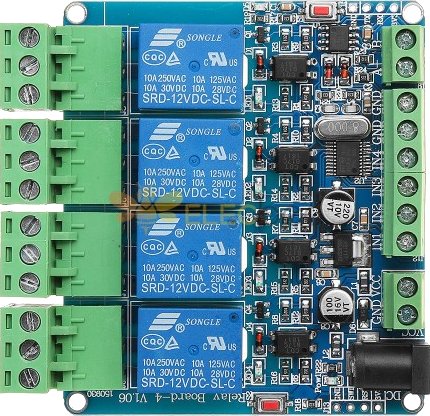
The Modbus 4CH I/O module (Manufacturer: Somewhere, Part ID: modbus) is a versatile 4-channel input/output device designed for seamless communication and control over a Modbus network. This module enables the integration of multiple sensors and actuators, making it ideal for industrial automation, home automation, and other applications requiring reliable and efficient data exchange.

Explore Projects Built with Modbus 4CH I/O

Use Cirkit Designer to design, explore, and prototype these projects online. Some projects support real-time simulation. Click "Open Project" to start designing instantly!
Raspberry Pi 4B-Controlled Relay System with Environmental Sensing and Power Monitoring
Image of smart_power_meter: A project utilizing Modbus 4CH I/O in a practical application
This circuit is designed to interface a Raspberry Pi 4B with various sensors and output devices. It includes a 4-channel relay for controlling external loads, an ADS1115 for analog-to-digital conversion of signals from a current sensor and a ZMPT101B voltage sensor, a DHT11 for temperature and humidity readings, and a 0.96" OLED display for data output. The Raspberry Pi 4B serves as the central controller, managing data acquisition from the sensors, processing the information, and driving the relay and display based on the sensor inputs and programmed logic.
Cirkit Designer LogoOpen Project in Cirkit Designer
Arduino UNO and Relay-Controlled RS485 Communication System
Image of Diagrama: A project utilizing Modbus 4CH I/O in a practical application
This circuit features an Arduino UNO microcontroller interfaced with a 4-channel relay module and a UART TTL to RS485 converter. The Arduino controls the relays via digital pins and communicates with the RS485 converter for serial communication, enabling control of external devices and communication over long distances.
Cirkit Designer LogoOpen Project in Cirkit Designer
ESP32-Based Industrial Control System with RS485 Communication and I2C Interface
Image of DRIVER TESTER : A project utilizing Modbus 4CH I/O in a practical application
This circuit integrates a microcontroller with a display, digital potentiometer, IO expander, and opto-isolator board for signal interfacing and isolation. It includes a UART to RS485 converter for serial communication and a power converter to step down voltage for the system. The circuit is designed for control and communication in an isolated and protected environment.
Cirkit Designer LogoOpen Project in Cirkit Designer
STM32 and Arduino UNO Based Dual RS485 Communication Interface
Image of STM to Arduino RS485: A project utilizing Modbus 4CH I/O in a practical application
This circuit consists of two microcontrollers, an STM32F103C8T6 and an Arduino UNO, each interfaced with separate RS485 transceiver modules for serial communication. The STM32F103C8T6 controls the RE (Receiver Enable) and DE (Driver Enable) pins of one RS485 module to manage its operation, and communicates via the A9 and A10 pins for DI (Data Input) and RO (Receiver Output), respectively. The Arduino UNO is similarly connected to another RS485 module, with digital pins D2 and D3 interfacing with DI and RO, and D8 controlling both RE and DE. The RS485 modules are connected to each other through their A and B differential communication lines, enabling serial data exchange between the two microcontrollers over a robust and long-distance capable RS485 network.
Cirkit Designer LogoOpen Project in Cirkit Designer

Explore Projects Built with Modbus 4CH I/O

Use Cirkit Designer to design, explore, and prototype these projects online. Some projects support real-time simulation. Click "Open Project" to start designing instantly!
Image of smart_power_meter: A project utilizing Modbus 4CH I/O in a practical application
Raspberry Pi 4B-Controlled Relay System with Environmental Sensing and Power Monitoring
This circuit is designed to interface a Raspberry Pi 4B with various sensors and output devices. It includes a 4-channel relay for controlling external loads, an ADS1115 for analog-to-digital conversion of signals from a current sensor and a ZMPT101B voltage sensor, a DHT11 for temperature and humidity readings, and a 0.96" OLED display for data output. The Raspberry Pi 4B serves as the central controller, managing data acquisition from the sensors, processing the information, and driving the relay and display based on the sensor inputs and programmed logic.
Cirkit Designer LogoOpen Project in Cirkit Designer
Image of Diagrama: A project utilizing Modbus 4CH I/O in a practical application
Arduino UNO and Relay-Controlled RS485 Communication System
This circuit features an Arduino UNO microcontroller interfaced with a 4-channel relay module and a UART TTL to RS485 converter. The Arduino controls the relays via digital pins and communicates with the RS485 converter for serial communication, enabling control of external devices and communication over long distances.
Cirkit Designer LogoOpen Project in Cirkit Designer
Image of DRIVER TESTER : A project utilizing Modbus 4CH I/O in a practical application
ESP32-Based Industrial Control System with RS485 Communication and I2C Interface
This circuit integrates a microcontroller with a display, digital potentiometer, IO expander, and opto-isolator board for signal interfacing and isolation. It includes a UART to RS485 converter for serial communication and a power converter to step down voltage for the system. The circuit is designed for control and communication in an isolated and protected environment.
Cirkit Designer LogoOpen Project in Cirkit Designer
Image of STM to Arduino RS485: A project utilizing Modbus 4CH I/O in a practical application
STM32 and Arduino UNO Based Dual RS485 Communication Interface
This circuit consists of two microcontrollers, an STM32F103C8T6 and an Arduino UNO, each interfaced with separate RS485 transceiver modules for serial communication. The STM32F103C8T6 controls the RE (Receiver Enable) and DE (Driver Enable) pins of one RS485 module to manage its operation, and communicates via the A9 and A10 pins for DI (Data Input) and RO (Receiver Output), respectively. The Arduino UNO is similarly connected to another RS485 module, with digital pins D2 and D3 interfacing with DI and RO, and D8 controlling both RE and DE. The RS485 modules are connected to each other through their A and B differential communication lines, enabling serial data exchange between the two microcontrollers over a robust and long-distance capable RS485 network.
Cirkit Designer LogoOpen Project in Cirkit Designer

Common Applications and Use Cases

  • Industrial automation systems for monitoring and controlling machinery.
  • Home automation for managing lighting, HVAC, and security systems.
  • Data acquisition systems for collecting sensor data.
  • Remote control of actuators such as relays, motors, and solenoids.
  • Integration of legacy devices into modern Modbus-based networks.

Technical Specifications

Key Technical Details

  • Communication Protocol: Modbus RTU (RS-485)
  • Input Channels: 4 digital inputs (optically isolated)
  • Output Channels: 4 digital outputs (relay or transistor-based, depending on model)
  • Operating Voltage: 12V to 24V DC
  • Input Voltage Range: 0V to 24V DC
  • Output Current Rating: Up to 2A per channel
  • Baud Rate: Configurable (default: 9600 bps)
  • Parity: None, Even, or Odd (configurable)
  • Stop Bits: 1 or 2 (configurable)
  • Operating Temperature: -20°C to 70°C
  • Dimensions: 100mm x 80mm x 25mm

Pin Configuration and Descriptions

Power and Communication Terminals

Pin Name Description
V+ Positive power supply (12V-24V DC)
GND Ground (0V)
A RS-485 communication line A
B RS-485 communication line B

Input Terminals

Pin Name Description
IN1 Digital input channel 1
IN2 Digital input channel 2
IN3 Digital input channel 3
IN4 Digital input channel 4
GND Common ground for input signals

Output Terminals

Pin Name Description
OUT1 Digital output channel 1
OUT2 Digital output channel 2
OUT3 Digital output channel 3
OUT4 Digital output channel 4
COM Common terminal for output signals

Usage Instructions

How to Use the Component in a Circuit

  1. Power Connection: Connect the V+ and GND terminals to a 12V-24V DC power supply.
  2. Communication Setup: Connect the A and B terminals to the RS-485 bus of your Modbus master device (e.g., PLC, PC, or microcontroller).
  3. Input Connections: Connect sensors or switches to the IN1-IN4 terminals, ensuring the common ground (GND) is shared.
  4. Output Connections: Connect actuators (e.g., relays, motors) to the OUT1-OUT4 terminals, using the COM terminal as the common connection.
  5. Configuration: Set the Modbus address, baud rate, parity, and stop bits using the DIP switches or configuration software (refer to the manufacturer's manual for details).

Important Considerations and Best Practices

  • Ensure proper termination resistors are used on the RS-485 bus to prevent signal reflections.
  • Avoid exceeding the maximum current rating (2A) for each output channel.
  • Use optically isolated inputs to protect the module from voltage spikes or noise.
  • Verify the Modbus address and communication settings to avoid conflicts on the network.
  • Use shielded twisted-pair cables for RS-485 communication to minimize interference.

Example: Connecting to an Arduino UNO

Below is an example of how to control the Modbus 4CH I/O module using an Arduino UNO and the ModbusMaster library.

Arduino Code Example

#include <ModbusMaster.h>

// Instantiate ModbusMaster object
ModbusMaster node;

// Define the Modbus slave ID of the 4CH I/O module
#define SLAVE_ID 1

void setup() {
  // Initialize serial communication for debugging
  Serial.begin(9600);
  
  // Initialize RS-485 communication (using pins 0 and 1 for Arduino UNO)
  Serial1.begin(9600); // Adjust baud rate as per module configuration
  
  // Assign the RS-485 serial port to the ModbusMaster object
  node.begin(SLAVE_ID, Serial1);
}

void loop() {
  uint8_t result;
  
  // Example: Turn ON output channel 1
  result = node.writeSingleCoil(0x0000, 1); // Address 0x0000 corresponds to OUT1
  if (result == node.ku8MBSuccess) {
    Serial.println("Output 1 turned ON successfully.");
  } else {
    Serial.print("Error: ");
    Serial.println(result, HEX);
  }
  
  delay(1000); // Wait for 1 second
  
  // Example: Turn OFF output channel 1
  result = node.writeSingleCoil(0x0000, 0); // Address 0x0000 corresponds to OUT1
  if (result == node.ku8MBSuccess) {
    Serial.println("Output 1 turned OFF successfully.");
  } else {
    Serial.print("Error: ");
    Serial.println(result, HEX);
  }
  
  delay(1000); // Wait for 1 second
}

Troubleshooting and FAQs

Common Issues and Solutions

  1. No Communication with the Module

    • Verify the RS-485 connections (A and B lines) and ensure they are not swapped.
    • Check the Modbus address and communication settings (baud rate, parity, stop bits).
    • Ensure the master device is configured to communicate with the correct slave ID.
  2. Inputs Not Responding

    • Confirm that the input voltage levels are within the specified range (0V-24V DC).
    • Check the wiring and ensure the common ground (GND) is properly connected.
  3. Outputs Not Activating

    • Verify that the connected actuators are within the output current rating (2A per channel).
    • Check the COM terminal connection and ensure it is properly wired.
  4. Intermittent Communication Errors

    • Use shielded twisted-pair cables for RS-485 communication.
    • Add termination resistors (120Ω) at both ends of the RS-485 bus.

FAQs

Q: Can I use this module with a Modbus TCP network?
A: No, this module is designed for Modbus RTU (RS-485) communication. You would need a Modbus RTU-to-TCP gateway for integration with a Modbus TCP network.

Q: How do I change the Modbus address of the module?
A: The Modbus address can be configured using the DIP switches or configuration software provided by the manufacturer. Refer to the manufacturer's manual for detailed instructions.

Q: What happens if I exceed the output current rating?
A: Exceeding the 2A current rating may damage the output channels. Use external relays or drivers for high-current loads.

Q: Can I use this module in outdoor environments?
A: The module is not weatherproof. Use an appropriate enclosure to protect it from moisture, dust, and extreme temperatures.