
How to Use Adafruit AP3429 3.3V Buck: Examples, Pinouts, and Specs
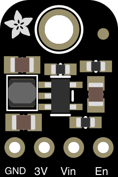
 Design with Adafruit AP3429 3.3V Buck in Cirkit Designer
Introduction
The Adafruit AP3429 3.3V Buck (Manufacturer Part ID: 4711) is a compact and efficient DC-DC buck converter designed to step down input voltages to a stable 3.3V output. This component is ideal for powering microcontrollers, sensors, and other low-voltage devices in embedded systems. Its high efficiency and small form factor make it a popular choice for portable and battery-powered applications.
Explore Projects Built with Adafruit AP3429 3.3V Buck
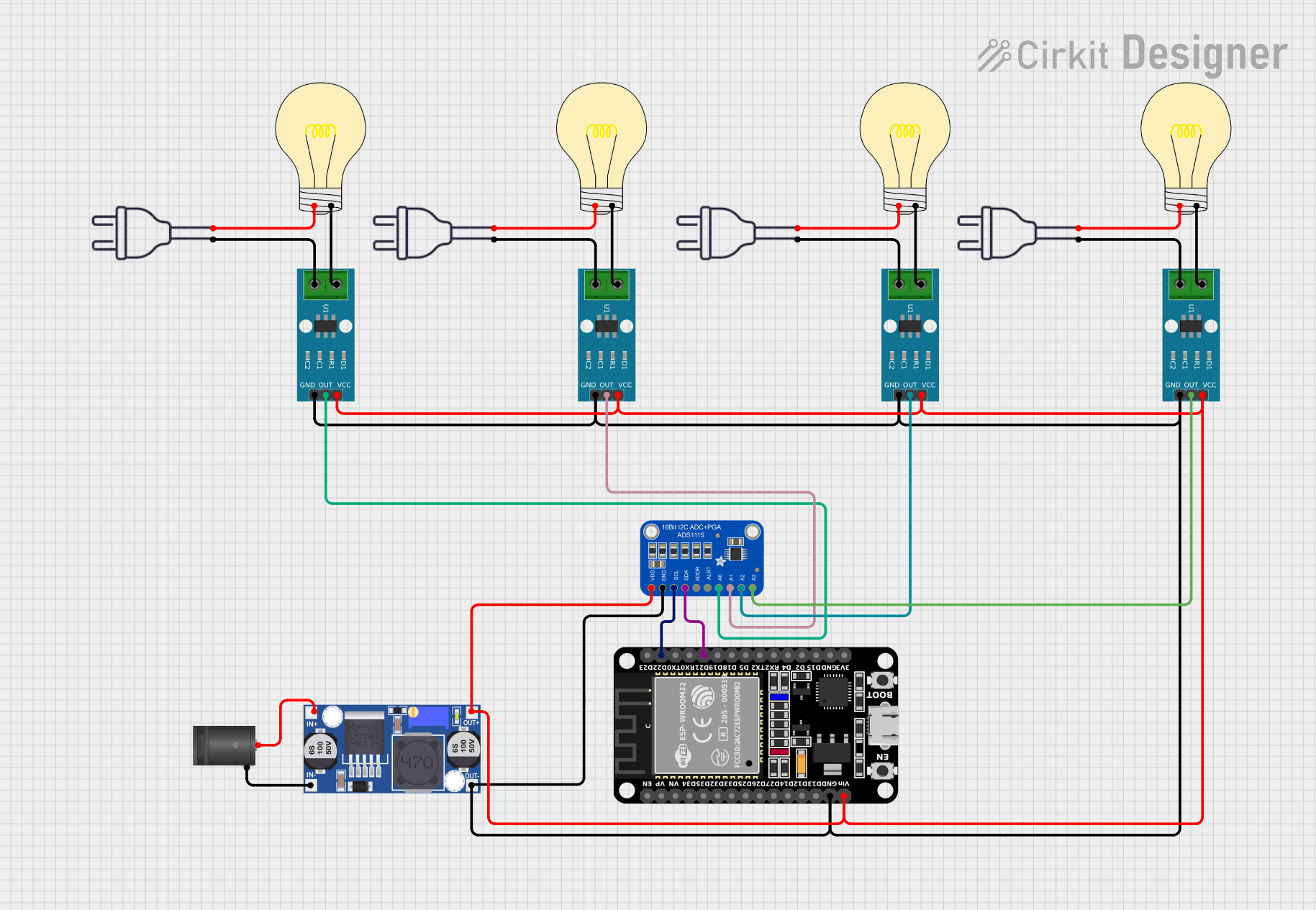 Open Project in Cirkit Designer
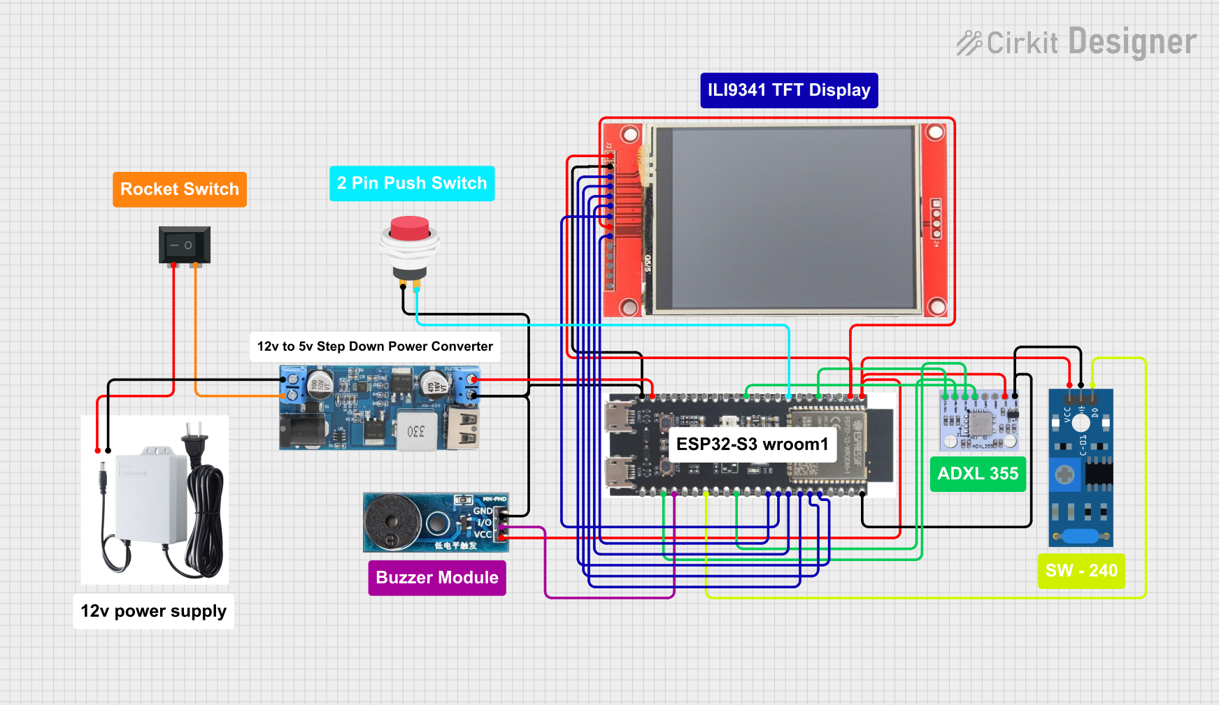 Open Project in Cirkit Designer
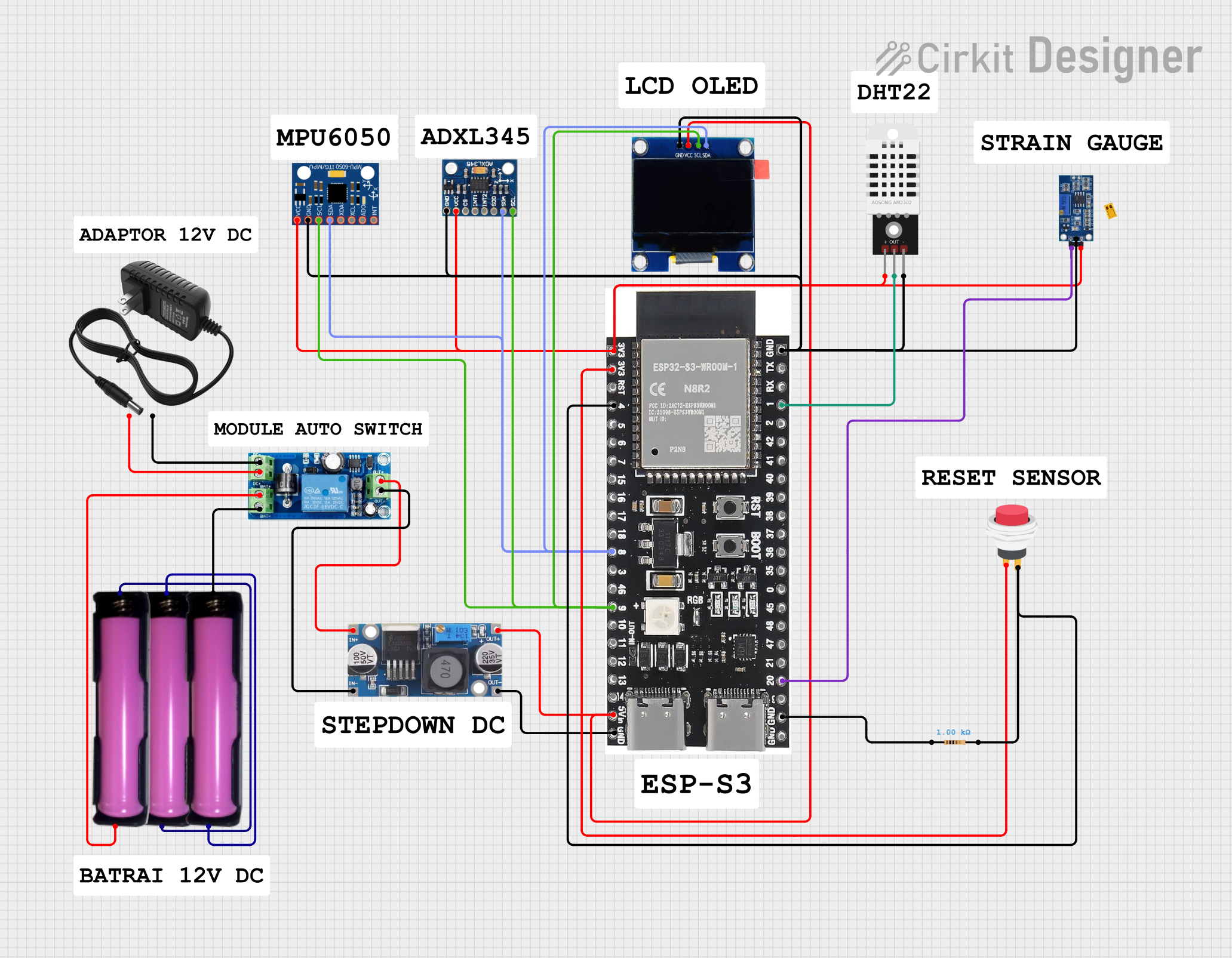 Open Project in Cirkit Designer
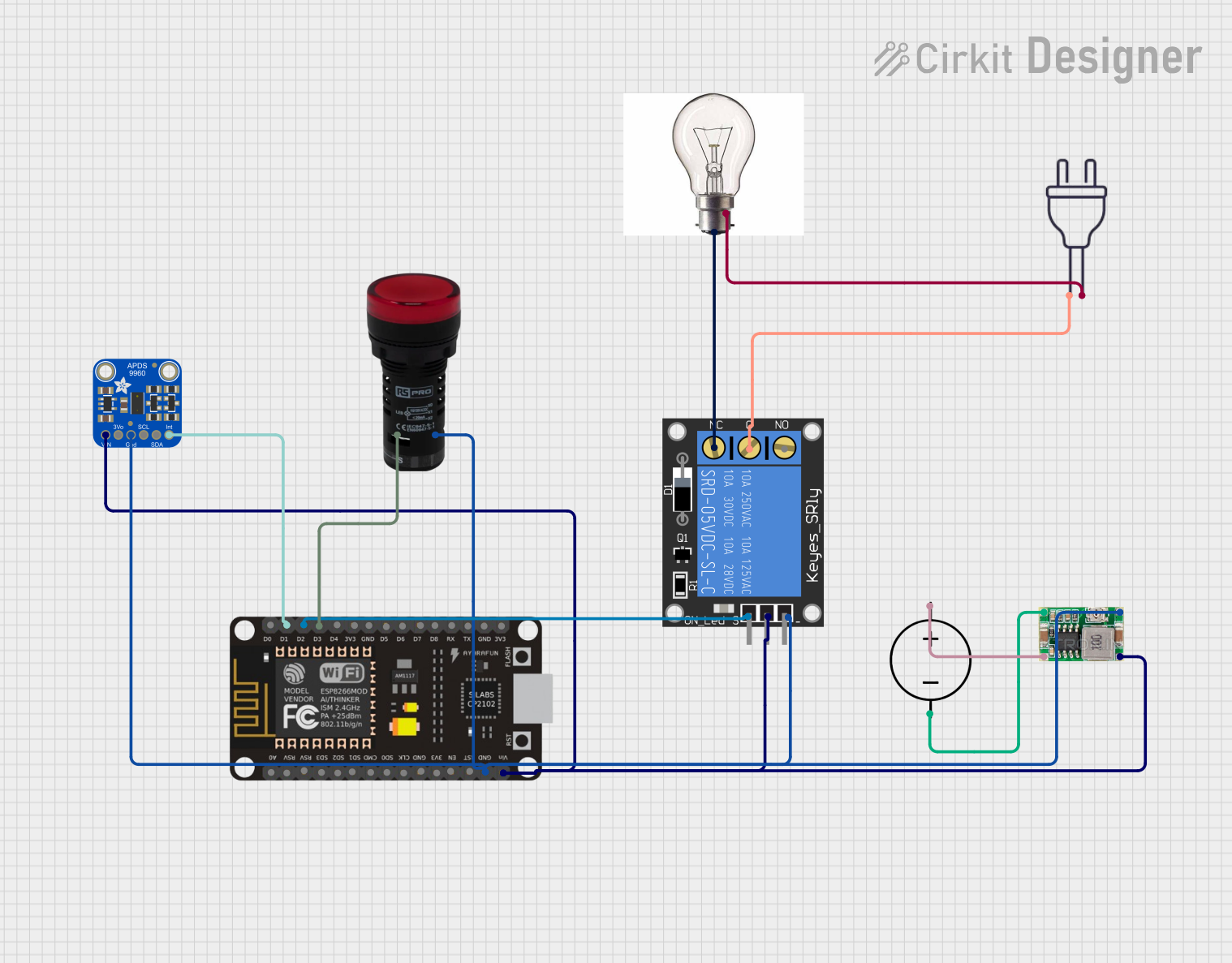 Open Project in Cirkit Designer
Explore Projects Built with Adafruit AP3429 3.3V Buck
Open Project in Cirkit DesignerOpen Project in Cirkit DesignerOpen Project in Cirkit DesignerOpen Project in Cirkit DesignerCommon Applications
- Powering 3.3V microcontrollers (e.g., ESP32, STM32, etc.)
- Supplying power to low-voltage sensors and modules
- Battery-powered devices requiring efficient voltage regulation
- General-purpose 3.3V power supply for prototyping and development boards
Technical Specifications
The following table outlines the key technical details of the Adafruit AP3429 3.3V Buck:
| Parameter | Value |
|---|---|
| Input Voltage Range | 4.5V to 5.5V |
| Output Voltage | 3.3V (fixed) |
| Maximum Output Current | 2A |
| Efficiency | Up to 95% |
| Switching Frequency | 1.5 MHz |
| Operating Temperature | -40°C to +85°C |
| Dimensions | 10mm x 10mm x 4mm |
Pin Configuration and Descriptions
The Adafruit AP3429 3.3V Buck has the following pinout:
| Pin Name | Description |
|---|---|
| VIN | Input voltage (4.5V to 5.5V). Connect to power source. |
| GND | Ground. Connect to the ground of the circuit. |
| VOUT | Regulated 3.3V output. Connect to the load. |
| EN | Enable pin. Pull high to enable the converter, low to disable. |
Usage Instructions
How to Use the Adafruit AP3429 3.3V Buck in a Circuit
Connect the Input Voltage (VIN):
- Provide a stable input voltage between 4.5V and 5.5V to the VIN pin.
- Ensure the input voltage is within the specified range to avoid damage.
Connect the Ground (GND):
- Connect the GND pin to the ground of your circuit.
Connect the Output Voltage (VOUT):
- Connect the VOUT pin to the load that requires a 3.3V power supply.
- Ensure the load does not exceed the maximum output current of 2A.
Enable the Converter (Optional):
- To enable the converter, pull the EN pin high (connect to VIN or a logic high signal).
- To disable the converter, pull the EN pin low (connect to GND).
Add Decoupling Capacitors:
- Place a 10µF capacitor close to the VIN pin to stabilize the input voltage.
- Place a 22µF capacitor close to the VOUT pin to ensure a stable output voltage.
Important Considerations and Best Practices
Thermal Management:
The AP3429 is highly efficient, but at high currents, it may generate heat. Ensure proper ventilation or use a heatsink if necessary.Input Voltage Stability:
Use a stable and noise-free input voltage source to maintain consistent performance.Load Requirements:
Verify that the total current draw of your load does not exceed 2A to prevent overloading the converter.
Example: Using the AP3429 with an Arduino UNO
The Adafruit AP3429 can be used to power an Arduino UNO by stepping down a 5V input to 3.3V for peripherals. Below is an example of connecting the AP3429 to an Arduino UNO:
// Example: Powering a 3.3V sensor with the AP3429 and Arduino UNO

// Connect the AP3429 as follows:
// VIN -> 5V power source (e.g., USB or battery)
// GND -> Arduino GND
// VOUT -> Sensor VCC (3.3V)
// EN -> VIN (to enable the converter)

// Arduino code to read data from a 3.3V sensor
const int sensorPin = A0; // Analog pin connected to the sensor output

void setup() {
  Serial.begin(9600); // Initialize serial communication
  pinMode(sensorPin, INPUT); // Set sensor pin as input
}

void loop() {
  int sensorValue = analogRead(sensorPin); // Read sensor value
  float voltage = sensorValue * (3.3 / 1023.0); // Convert to voltage
  Serial.print("Sensor Voltage: ");
  Serial.print(voltage);
  Serial.println(" V");
  delay(1000); // Wait 1 second before next reading
}
Troubleshooting and FAQs
Common Issues and Solutions
No Output Voltage (VOUT):
- Cause: EN pin is not pulled high.
- Solution: Ensure the EN pin is connected to VIN or a logic high signal.
Overheating:
- Cause: Excessive current draw or insufficient ventilation.
- Solution: Reduce the load current or improve thermal management (e.g., add a heatsink).
Unstable Output Voltage:
- Cause: Missing or insufficient decoupling capacitors.
- Solution: Add a 10µF capacitor to VIN and a 22µF capacitor to VOUT.
Low Efficiency:
- Cause: Input voltage is too close to the output voltage.
- Solution: Use an input voltage closer to the upper limit of the specified range (e.g., 5V).
FAQs
Q: Can the AP3429 be used with a 12V input?
A: No, the AP3429 supports an input voltage range of 4.5V to 5.5V. Using a 12V input will damage the component.
Q: Is the output voltage adjustable?
A: No, the AP3429 provides a fixed 3.3V output.
Q: Can I use the AP3429 to power a Raspberry Pi?
A: No, the Raspberry Pi typically requires 5V input. The AP3429 is designed for 3.3V applications.
Q: What is the maximum load current?
A: The AP3429 can supply up to 2A of current to the load.
Q: Does the AP3429 have reverse polarity protection?
A: No, the AP3429 does not include reverse polarity protection. Ensure correct polarity when connecting the input voltage.