How to Use 256kb (32kx8) SRAM: Examples, Pinouts, and Specs
Introduction
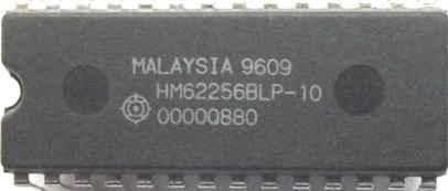
The IC62C256 is a high-speed, low-power static random-access memory (SRAM) chip manufactured by Integrated Circuit Solution Inc.. It has a storage capacity of 256 kilobits, organized as 32,768 words of 8 bits each. Unlike dynamic RAM (DRAM), SRAM does not require periodic refreshing, making it ideal for applications requiring fast and reliable data storage.
Explore Projects Built with 256kb (32kx8) SRAM


Explore Projects Built with 256kb (32kx8) SRAM
Common Applications and Use Cases
- Microcontroller memory expansion: Provides additional memory for embedded systems.
- Cache memory: Used in processors for high-speed data access.
- Buffering: Temporary data storage in communication systems, printers, and video devices.
- Data logging: Retains data in real-time systems.
- FPGA/ASIC designs: Used as scratchpad memory for custom hardware designs.
Technical Specifications
Key Technical Details
| Parameter | Value |
|---|---|
| Memory Organization | 32,768 words x 8 bits |
| Memory Capacity | 256 kilobits |
| Operating Voltage (Vcc) | 4.5V to 5.5V |
| Standby Current (Icc) | 1 µA (typical) |
| Operating Current (Icc) | 10 mA (typical) at 1 MHz |
| Access Time | 55 ns, 70 ns, or 100 ns |
| Data Retention Voltage | 2.0V (minimum) |
| Package Types | 28-pin DIP, SOP, or TSOP |
| Operating Temperature | -40°C to +85°C (industrial) |
Pin Configuration and Descriptions
The IC62C256 SRAM chip is available in a 28-pin package. Below is the pinout and description:
| Pin No. | Pin Name | Type | Description |
|---|---|---|---|
| 1-15 | A0-A14 | Input | Address inputs used to select one of 32,768 memory locations. |
| 16 | CE | Input | Chip Enable: Activates the chip when LOW. |
| 17 | OE | Input | Output Enable: Enables data output when LOW. |
| 18 | WE | Input | Write Enable: Controls write operations when LOW. |
| 19-26 | I/O0-I/O7 | Input/Output | Data input/output pins for reading or writing 8-bit data. |
| 27 | Vcc | Power | Power supply pin (4.5V to 5.5V). |
| 28 | GND | Ground | Ground connection. |
Usage Instructions
How to Use the IC62C256 in a Circuit
- Power Supply: Connect the Vcc pin to a regulated 5V power supply and the GND pin to ground.
- Address Lines: Use the A0-A14 pins to select the desired memory location. These pins should be connected to the address bus of your microcontroller or processor.
- Data Lines: Connect the I/O0-I/O7 pins to the data bus of your system for reading or writing 8-bit data.
- Control Signals:
- CE (Chip Enable): Must be LOW to activate the chip.
- OE (Output Enable): Must be LOW to enable data output during a read operation.
- WE (Write Enable): Must be LOW to perform a write operation.
- Read Operation:
- Set CE and OE LOW, and WE HIGH.
- Provide the desired address on the address lines.
- Read the data from the data lines.
- Write Operation:
- Set CE and WE LOW, and OE HIGH.
- Provide the desired address on the address lines.
- Place the data to be written on the data lines.
Important Considerations and Best Practices
- Decoupling Capacitors: Place a 0.1 µF ceramic capacitor close to the Vcc pin to filter out noise.
- Unused Pins: Leave unused address or data pins unconnected or tie them to ground through a pull-down resistor.
- Timing Requirements: Ensure that the address, data, and control signals meet the timing specifications in the datasheet.
- Data Retention: If the chip is used in battery-backed applications, ensure the voltage does not drop below 2.0V.
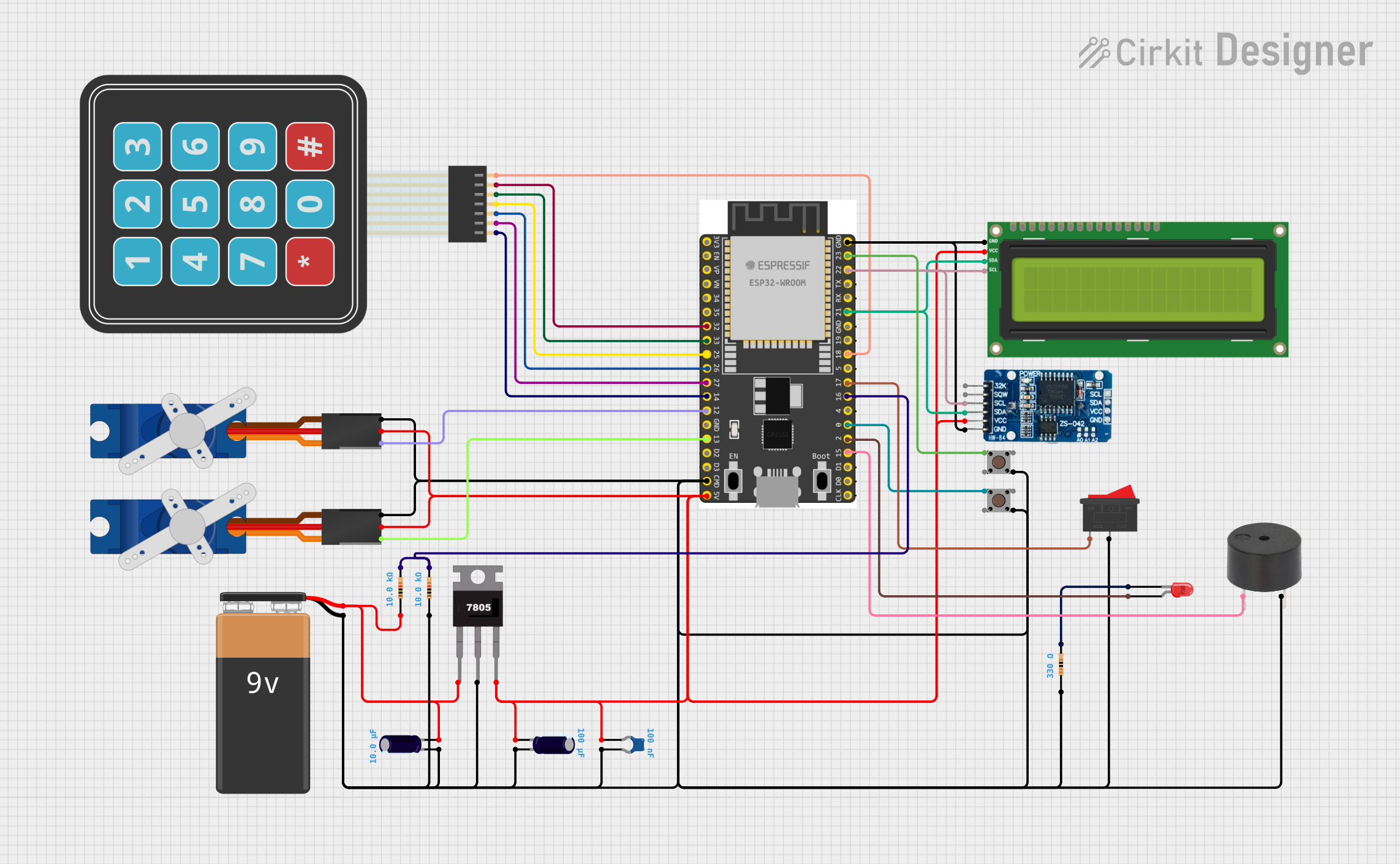
Example: Interfacing with Arduino UNO
Below is an example of how to interface the IC62C256 SRAM with an Arduino UNO for basic read and write operations:
// Define control pins
#define CE_PIN 8  // Chip Enable
#define OE_PIN 9  // Output Enable
#define WE_PIN 10 // Write Enable

// Define address and data pins
#define ADDR_PINS {2, 3, 4, 5, 6, 7, A0, A1, A2, A3, A4, A5, 11, 12, 13}
#define DATA_PINS {A0, A1, A2, A3, A4, A5, 11, 12}

// Function to write data to SRAM
void writeSRAM(uint16_t address, uint8_t data) {
  // Set address pins
  for (int i = 0; i < 15; i++) {
    digitalWrite(ADDR_PINS[i], (address >> i) & 0x01);
  }

  // Set data pins to output mode and write data
  for (int i = 0; i < 8; i++) {
    pinMode(DATA_PINS[i], OUTPUT);
    digitalWrite(DATA_PINS[i], (data >> i) & 0x01);
  }

  // Perform write operation
  digitalWrite(CE_PIN, LOW);
  digitalWrite(WE_PIN, LOW);
  delayMicroseconds(1); // Ensure timing requirements
  digitalWrite(WE_PIN, HIGH);
  digitalWrite(CE_PIN, HIGH);
}

// Function to read data from SRAM
uint8_t readSRAM(uint16_t address) {
  uint8_t data = 0;

  // Set address pins
  for (int i = 0; i < 15; i++) {
    digitalWrite(ADDR_PINS[i], (address >> i) & 0x01);
  }

  // Set data pins to input mode
  for (int i = 0; i < 8; i++) {
    pinMode(DATA_PINS[i], INPUT);
  }

  // Perform read operation
  digitalWrite(CE_PIN, LOW);
  digitalWrite(OE_PIN, LOW);
  delayMicroseconds(1); // Ensure timing requirements

  // Read data from data pins
  for (int i = 0; i < 8; i++) {
    data |= (digitalRead(DATA_PINS[i]) << i);
  }

  digitalWrite(OE_PIN, HIGH);
  digitalWrite(CE_PIN, HIGH);

  return data;
}

void setup() {
  // Initialize control pins
  pinMode(CE_PIN, OUTPUT);
  pinMode(OE_PIN, OUTPUT);
  pinMode(WE_PIN, OUTPUT);

  // Set control pins to default states
  digitalWrite(CE_PIN, HIGH);
  digitalWrite(OE_PIN, HIGH);
  digitalWrite(WE_PIN, HIGH);
}

void loop() {
  // Example usage: Write and read data
  writeSRAM(0x1234, 0xAB); // Write 0xAB to address 0x1234
  uint8_t data = readSRAM(0x1234); // Read data from address 0x1234
}
Troubleshooting and FAQs
Common Issues and Solutions
No Data Output During Read Operation:
- Ensure that CE and OE are LOW during the read operation.
- Verify that the address lines are correctly set.
Incorrect Data Written or Read:
- Check for timing violations in the control signals.
- Ensure that the data lines are not floating or shorted.
High Power Consumption:
- Verify that the chip is in standby mode (CE HIGH) when not in use.
- Check for excessive noise on the power supply.
Data Loss in Battery-Backed Applications:
- Ensure that the supply voltage does not drop below 2.0V.
- Use a reliable battery with sufficient capacity.
FAQs
Q: Can the IC62C256 be used with 3.3V systems?
A: No, the IC62C256 requires a supply voltage of 4.5V to 5.5V. Use a level shifter for 3.3V systems.
Q: How do I ensure data integrity during power loss?
A: Use a battery backup circuit and ensure the voltage does not drop below the data retention voltage of 2.0V.
Q: What is the maximum operating frequency of the IC62C256?
A: The maximum