How to Use 5V Regulator: Examples, Pinouts, and Specs
Introduction
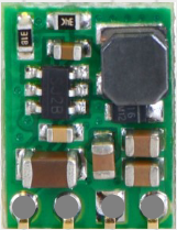
The Pololu D36V6F5 is a compact and efficient 5V regulator designed to provide a stable 5-volt output from a higher input voltage. This step-down (buck) voltage regulator is ideal for powering sensitive electronic devices and circuits that require a consistent 5V supply. Its small size and high efficiency make it suitable for a wide range of applications, including robotics, embedded systems, and portable electronics.
Explore Projects Built with 5V Regulator


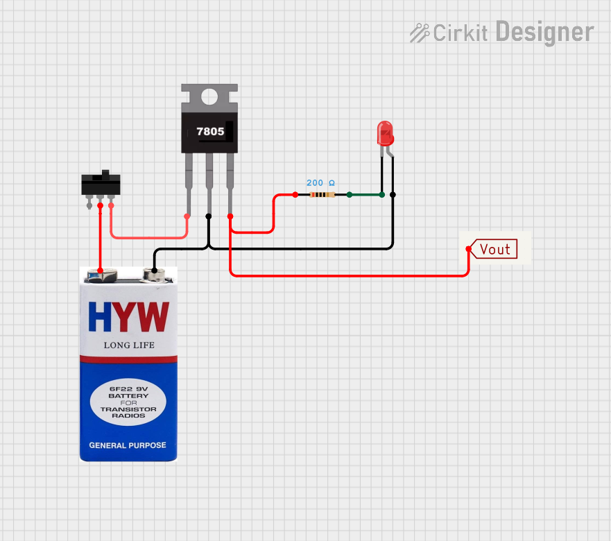

Explore Projects Built with 5V Regulator
Common Applications and Use Cases
- Powering microcontrollers, sensors, and modules in embedded systems
- Providing a stable 5V supply for Arduino, Raspberry Pi, and other development boards
- Regulating power in battery-powered devices
- Supplying power to communication modules (e.g., Wi-Fi, Bluetooth, GSM)
- Robotics and automation systems
Technical Specifications
The Pololu D36V6F5 5V regulator is designed with robust features to ensure reliable performance. Below are its key technical details:
Key Technical Details
| Parameter | Value |
|---|---|
| Input Voltage Range | 6V to 50V |
| Output Voltage | 5V (regulated) |
| Maximum Output Current | 600 mA |
| Efficiency | Up to 90% (depending on input voltage) |
| Quiescent Current | ~200 µA |
| Operating Temperature | -40°C to +85°C |
| Dimensions | 0.4" × 0.5" × 0.1" (10 × 13 × 3 mm) |
| Weight | 0.5 g |
Pin Configuration and Descriptions
The D36V6F5 regulator has three pins for easy integration into circuits. The table below describes each pin:
| Pin Name | Pin Type | Description |
|---|---|---|
| VIN | Input | Connect to the input voltage source (6V-50V). |
| GND | Ground | Connect to the ground of the circuit. |
| VOUT | Output | Provides the regulated 5V output. |
Usage Instructions
How to Use the Component in a Circuit
Connect the Input Voltage (VIN):
- Attach the VIN pin to a power source with a voltage between 6V and 50V. Ensure the input voltage is within this range to avoid damaging the regulator.
Connect the Ground (GND):
- Connect the GND pin to the ground of your circuit. This is essential for proper operation.
Connect the Output Voltage (VOUT):
- Use the VOUT pin to power your 5V devices. Ensure the total current draw does not exceed 600 mA.
Add Capacitors (Optional):
- For improved stability, you can add a capacitor (e.g., 10 µF) across the input and output pins. This is especially useful in circuits with high noise or fluctuating loads.
Important Considerations and Best Practices
Heat Dissipation:
The regulator is highly efficient, but if operating near its maximum current limit, ensure adequate ventilation or heat sinking to prevent overheating.Input Voltage Range:
Always verify that the input voltage is within the specified range (6V-50V). Exceeding this range can permanently damage the regulator.Polarity Protection:
The D36V6F5 does not have built-in reverse polarity protection. Double-check your connections to avoid damage.Arduino UNO Example:
The D36V6F5 can be used to power an Arduino UNO by connecting the VOUT pin to the 5V pin on the Arduino. Below is an example of how to use the regulator with an Arduino UNO:
// Example: Reading a sensor powered by the D36V6F5 regulator
// Ensure the regulator's VOUT is connected to the Arduino's 5V pin
// and the sensor's power pin.

const int sensorPin = A0; // Analog pin connected to the sensor output
int sensorValue = 0;      // Variable to store the sensor reading

void setup() {
  Serial.begin(9600); // Initialize serial communication
  pinMode(sensorPin, INPUT); // Set the sensor pin as input
}

void loop() {
  sensorValue = analogRead(sensorPin); // Read the sensor value
  Serial.print("Sensor Value: ");
  Serial.println(sensorValue); // Print the sensor value to the Serial Monitor
  delay(1000); // Wait for 1 second before the next reading
}
Troubleshooting and FAQs
Common Issues and Solutions
No Output Voltage:
- Cause: Input voltage is below 6V or connections are incorrect.
- Solution: Verify that the input voltage is within the 6V-50V range and check all connections.
Overheating:
- Cause: Excessive current draw or poor ventilation.
- Solution: Ensure the load does not exceed 600 mA and provide adequate cooling.
Fluctuating Output Voltage:
- Cause: Insufficient input or output capacitance.
- Solution: Add a capacitor (e.g., 10 µF) across the input and output pins.
Regulator Not Working After Connection:
- Cause: Reverse polarity or input voltage exceeded 50V.
- Solution: Replace the regulator and ensure correct polarity and voltage range in future use.
FAQs
Q1: Can I use the D36V6F5 to power a Raspberry Pi?
A1: No, the D36V6F5 is not suitable for powering a Raspberry Pi, as the current requirements of the Raspberry Pi typically exceed 600 mA.
Q2: Is the regulator protected against short circuits?
A2: No, the D36V6F5 does not have built-in short-circuit protection. Avoid shorting the output to ground.
Q3: Can I use this regulator with a 12V car battery?
A3: Yes, the D36V6F5 can be used with a 12V car battery, as the input voltage is within the supported range.
Q4: What happens if I exceed the maximum current rating?
A4: Exceeding 600 mA can cause the regulator to overheat or shut down. Always ensure the load stays within the specified limit.