How to Use RoboClaw 2x7a: Examples, Pinouts, and Specs
Introduction
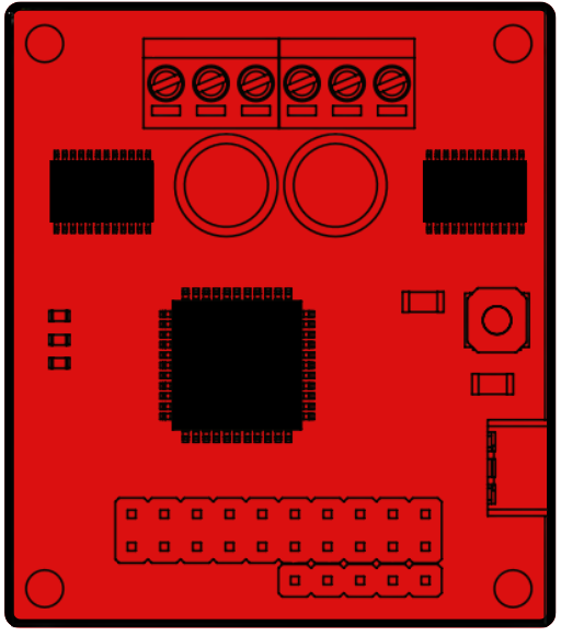
The RoboClaw 2x7a, manufactured by Basic Micro (Part ID: IMC404), is a dual-channel motor controller designed for driving DC motors. It supports up to 7 amps per channel and offers advanced control features, including speed and direction control, encoder feedback, and PWM input. This versatile motor controller is ideal for robotics, automation systems, and other applications requiring precise motor control.
Explore Projects Built with RoboClaw 2x7a
Explore Projects Built with RoboClaw 2x7a
Common Applications
- Robotics and autonomous vehicles
- Conveyor belt systems
- Automated machinery
- Remote-controlled vehicles
- Hobbyist and educational projects
Technical Specifications
Key Technical Details
| Parameter | Specification |
|---|---|
| Manufacturer | Basic Micro |
| Part ID | IMC404 |
| Channels | 2 (dual-channel) |
| Continuous Current | 7A per channel |
| Peak Current | 15A per channel (for short durations) |
| Input Voltage Range | 6V to 34V |
| Control Interfaces | USB, TTL Serial, RC (PWM), Analog |
| Encoder Support | Quadrature encoders |
| Communication Protocols | Packetized Serial, Simple Serial |
| Dimensions | 2.5" x 2.0" x 0.5" (63.5mm x 50.8mm x 12.7mm) |
| Weight | 1.5 oz (42.5g) |
Pin Configuration and Descriptions
| Pin Name | Description |
|---|---|
| M1A, M1B | Motor 1 output terminals (connect to DC motor 1) |
| M2A, M2B | Motor 2 output terminals (connect to DC motor 2) |
| B+ | Positive battery input (6V to 34V) |
| B- | Negative battery input (ground) |
| S1, S2 | Encoder inputs for Motor 1 (A and B channels) |
| S3, S4 | Encoder inputs for Motor 2 (A and B channels) |
| GND | Ground reference for control signals |
| 5V Out | 5V regulated output (can power external devices, max 100mA) |
| RX, TX | TTL Serial communication pins (for UART interface) |
| A1, A2 | Analog input pins (for speed and direction control) |
| RC1, RC2 | RC (PWM) input pins (for remote control signals) |
| USB | USB interface for configuration and control |
Usage Instructions
Using the RoboClaw 2x7a in a Circuit
- Power Supply: Connect a DC power source (6V to 34V) to the
B+andB-terminals. Ensure the power supply can handle the current requirements of your motors. - Motor Connections: Connect the DC motors to the
M1A/M1BandM2A/M2Bterminals. Ensure proper polarity for desired motor direction. - Control Interface: Choose a control method (USB, TTL Serial, RC, or Analog):
- For USB control, connect the RoboClaw to a computer using a USB cable.
- For TTL Serial, connect the
RXandTXpins to a microcontroller (e.g., Arduino). - For RC control, connect RC receiver outputs to
RC1andRC2. - For Analog control, connect potentiometers or analog signals to
A1andA2.
- Encoder Feedback (Optional): If using encoders, connect the encoder outputs to the
S1/S2(Motor 1) andS3/S4(Motor 2) pins. - Configuration: Use the Basic Micro Motion Studio software (available on the manufacturer's website) to configure the RoboClaw for your application.
Important Considerations
- Heat Dissipation: The RoboClaw 2x7a can generate heat during operation. Ensure adequate ventilation or use a heatsink if necessary.
- Current Limits: Avoid exceeding the continuous current rating of 7A per channel to prevent damage.
- Wiring: Use appropriately rated wires for power and motor connections to handle the required current.
- Safety: Always disconnect power before making wiring changes.
Example: Controlling the RoboClaw with an Arduino UNO
Below is an example of controlling the RoboClaw 2x7a using an Arduino UNO via TTL Serial communication:
#include <SoftwareSerial.h>

// Define RX and TX pins for SoftwareSerial
#define ROBOCLAW_RX 10  // Arduino pin connected to RoboClaw TX
#define ROBOCLAW_TX 11  // Arduino pin connected to RoboClaw RX

// Create a SoftwareSerial object
SoftwareSerial roboclaw(ROBOCLAW_RX, ROBOCLAW_TX);

void setup() {
  // Initialize serial communication with RoboClaw
  roboclaw.begin(38400); // Default baud rate for RoboClaw
  Serial.begin(9600);    // For debugging with Serial Monitor

  // Send a command to stop both motors
  sendCommand(0x00, 0); // Command 0x00 stops the motors
}

void loop() {
  // Example: Set Motor 1 to 50% forward speed
  sendCommand(0x01, 64); // Command 0x01 sets Motor 1 speed (0-127)
  delay(2000);

  // Example: Set Motor 2 to 50% reverse speed
  sendCommand(0x02, 64); // Command 0x02 sets Motor 2 speed (0-127)
  delay(2000);

  // Stop both motors
  sendCommand(0x00, 0);
  delay(2000);
}

// Function to send a command to the RoboClaw
void sendCommand(uint8_t command, uint8_t value) {
  roboclaw.write(command); // Send command byte
  roboclaw.write(value);   // Send value byte
  roboclaw.write(0x00);    // Send checksum (for simplicity, set to 0)
}
Notes:
- Replace
sendCommandlogic with the appropriate checksum calculation for robust communication. - Ensure the RoboClaw is configured for TTL Serial mode.
Troubleshooting and FAQs
Common Issues
Motors Not Running:
- Verify power supply voltage and current ratings.
- Check motor connections and polarity.
- Ensure the control interface is properly configured.
Overheating:
- Ensure adequate ventilation or use a heatsink.
- Avoid exceeding the continuous current rating.
Communication Errors:
- Check baud rate settings on both the RoboClaw and the microcontroller.
- Verify wiring for RX and TX connections.
Encoder Feedback Not Working:
- Ensure encoders are properly connected to the
S1/S2orS3/S4pins. - Verify encoder configuration in the Basic Micro Motion Studio software.
- Ensure encoders are properly connected to the
FAQs
Q: Can the RoboClaw 2x7a control brushless motors?
A: No, the RoboClaw 2x7a is designed for brushed DC motors only.
Q: What happens if I exceed the current rating?
A: The RoboClaw has built-in overcurrent protection, but exceeding the rating may cause thermal shutdown or permanent damage.
Q: Can I power the Arduino from the RoboClaw's 5V output?
A: Yes, but ensure the total current draw does not exceed 100mA.
Q: How do I update the RoboClaw firmware?
A: Use the Basic Micro Motion Studio software and follow the firmware update instructions provided by the manufacturer.