How to Use Relay 3P + NO + NC: Examples, Pinouts, and Specs
Introduction
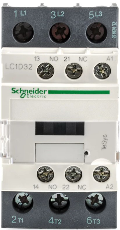
The Schneider Electric LC1D32U7 is a robust and versatile relay designed for industrial and commercial applications. It features three poles (3P) with both normally open (NO) and normally closed (NC) contacts, making it ideal for controlling and switching electrical circuits. This relay is commonly used in motor control, lighting systems, and automation processes where reliable switching is required.
Explore Projects Built with Relay 3P + NO + NC
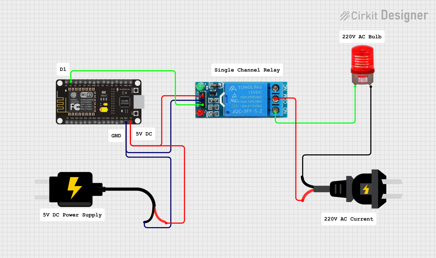
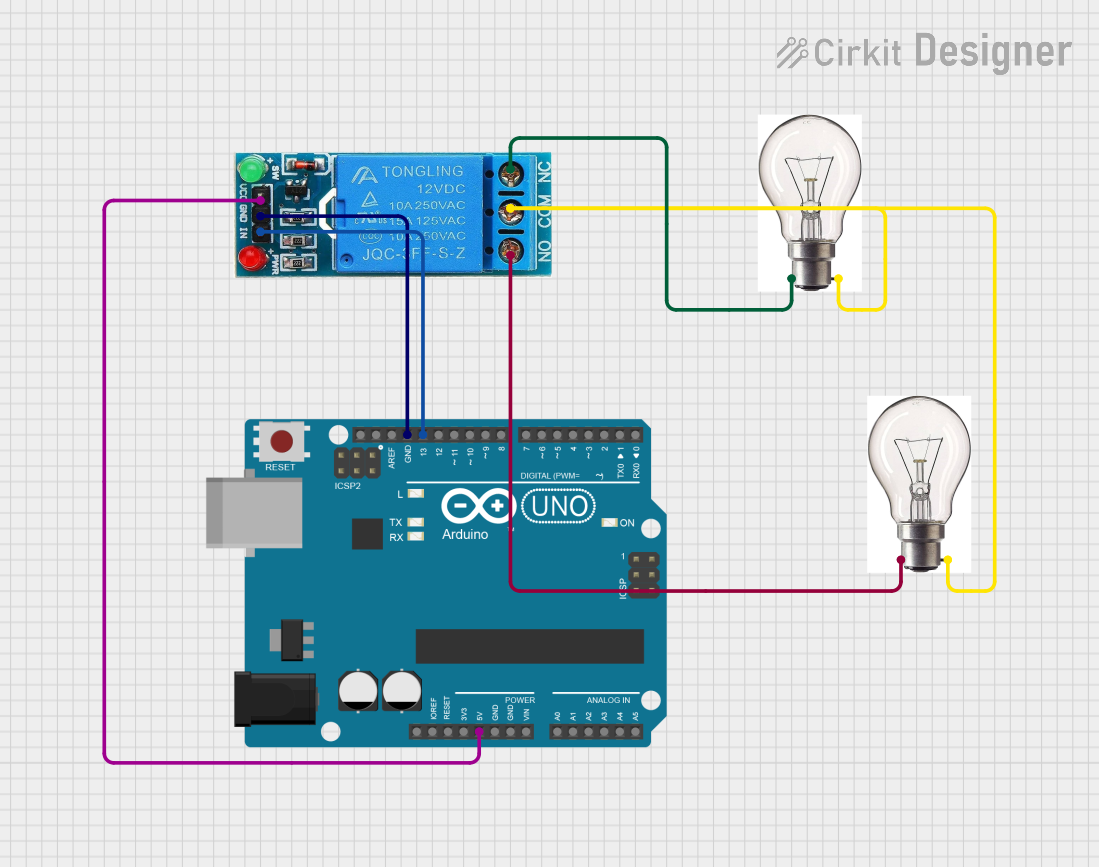
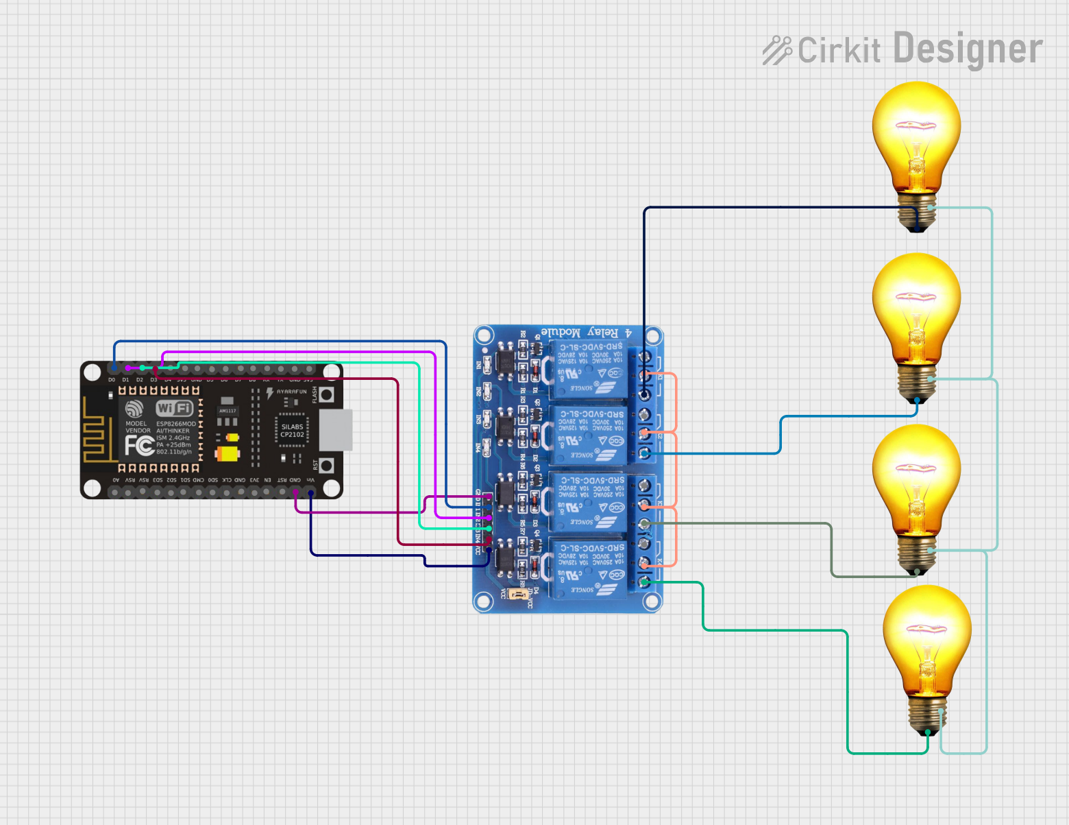
Explore Projects Built with Relay 3P + NO + NC
Common Applications:
- Motor starters and control systems
- Industrial automation and process control
- Lighting and HVAC systems
- Power distribution and circuit isolation
Technical Specifications
Key Technical Details:
| Parameter | Value |
|---|---|
| Manufacturer | Schneider Electric |
| Part Number | LC1D32U7 |
| Number of Poles | 3 (Three Poles) |
| Contact Configuration | Normally Open (NO) + Normally Closed (NC) |
| Rated Operational Voltage | Up to 690V AC |
| Rated Current | 32A |
| Coil Voltage | 110V AC (50/60 Hz) |
| Mechanical Durability | 10 million operations |
| Electrical Durability | 1 million operations |
| Mounting Type | DIN Rail or Panel Mount |
| Operating Temperature | -5°C to +60°C |
| Dimensions (H x W x D) | 85mm x 45mm x 90mm |
| Weight | 0.6 kg |
Pin Configuration and Descriptions:
The LC1D32U7 relay has a straightforward pin layout for its coil and contact terminals. Below is the pin configuration:
Coil Terminals:
| Pin Number | Description |
|---|---|
| A1 | Coil Input (Positive) |
| A2 | Coil Input (Negative) |
Contact Terminals:
| Pin Number | Description |
|---|---|
| L1, L2, L3 | Input Terminals for 3 Poles |
| T1, T2, T3 | Output Terminals for 3 Poles |
| 13, 14 | Normally Open (NO) Contact |
| 21, 22 | Normally Closed (NC) Contact |
Usage Instructions
How to Use the LC1D32U7 in a Circuit:
- Power the Coil: Connect the A1 and A2 terminals to a 110V AC power source. Ensure the polarity is correct.
- Connect the Load:
- For the main circuit, connect the input power lines to L1, L2, and L3.
- Connect the load (e.g., motor or lighting system) to T1, T2, and T3.
- Control Circuit: Use the NO (13-14) or NC (21-22) contacts for auxiliary control purposes, such as signaling or interlocking.
- Mounting: Secure the relay on a DIN rail or panel mount as per your setup requirements.
- Test the Circuit: After wiring, energize the coil to test the relay's operation. The NO contacts should close, and the NC contacts should open when the coil is powered.
Important Considerations:
- Voltage and Current Ratings: Ensure the relay's voltage and current ratings match your application to avoid damage.
- Inductive Loads: Use appropriate snubber circuits or surge suppressors when switching inductive loads like motors.
- Wiring: Double-check all connections to prevent short circuits or incorrect operation.
- Environment: Operate the relay within the specified temperature range and avoid exposure to moisture or dust.
Example: Connecting to an Arduino UNO
The LC1D32U7 can be controlled using an Arduino UNO by interfacing it with a relay driver circuit. Below is an example code snippet:
// Arduino code to control the LC1D32U7 relay using a digital pin
const int relayPin = 7; // Pin connected to the relay driver circuit

void setup() {
  pinMode(relayPin, OUTPUT); // Set the relay pin as an output
  digitalWrite(relayPin, LOW); // Ensure the relay is off initially
}

void loop() {
  digitalWrite(relayPin, HIGH); // Turn the relay ON
  delay(5000); // Keep it ON for 5 seconds
  digitalWrite(relayPin, LOW); // Turn the relay OFF
  delay(5000); // Keep it OFF for 5 seconds
}
Note: Use a transistor or relay driver module to interface the Arduino with the LC1D32U7, as the Arduino cannot directly drive the relay's coil.
Troubleshooting and FAQs
Common Issues and Solutions:
Relay Does Not Activate:
- Cause: Insufficient coil voltage or incorrect wiring.
- Solution: Verify the coil voltage (110V AC) and check the A1 and A2 connections.
Contacts Do Not Switch:
- Cause: Mechanical failure or incorrect load wiring.
- Solution: Inspect the relay for damage and ensure the load is connected to the correct terminals (L1-T1, L2-T2, L3-T3).
Excessive Heating:
- Cause: Overloading or poor ventilation.
- Solution: Ensure the load does not exceed the rated current (32A) and provide adequate ventilation.
Noise or Chattering:
- Cause: Unstable coil voltage or interference.
- Solution: Check the power supply for stability and use a filter if necessary.
FAQs:
Q: Can the LC1D32U7 be used with DC loads?
A: Yes, but ensure the load's voltage and current ratings are within the relay's specifications.Q: How do I protect the relay from voltage spikes?
A: Use a snubber circuit or varistor across the contacts to suppress voltage spikes, especially for inductive loads.Q: Can I use this relay for three-phase motors?
A: Yes, the LC1D32U7 is designed for three-phase motor control applications.Q: What is the lifespan of this relay?
A: The mechanical durability is 10 million operations, and the electrical durability is 1 million operations under rated conditions.
This concludes the documentation for the Schneider Electric LC1D32U7 relay. For further assistance, refer to the manufacturer's datasheet or contact technical support.