Cirkit Designer Logo
Cirkit Designer
Your all-in-one circuit design IDE
Home / 
Component Documentation

How to Use 2x2 Button Matrix: Examples, Pinouts, and Specs

Image of 2x2 Button Matrix
Cirkit Designer LogoDesign with 2x2 Button Matrix in Cirkit Designer

Introduction

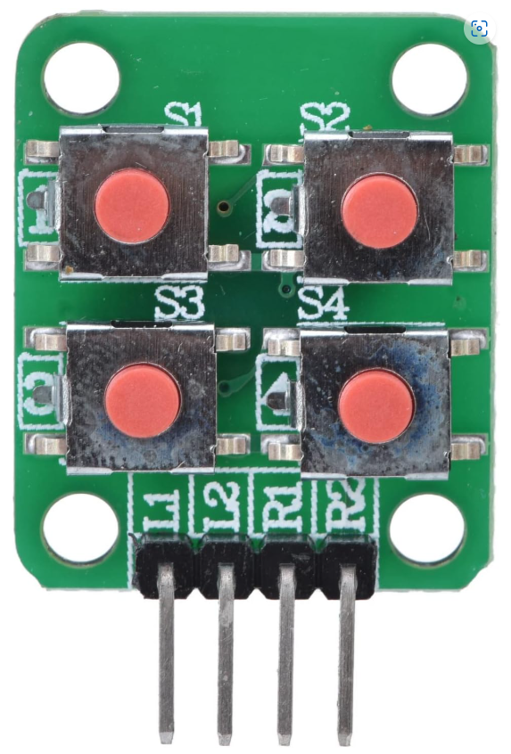
The 2x2 Button Matrix is a compact grid of four buttons arranged in two rows and two columns. This design allows for multiple button presses to be detected using fewer input pins, making it an efficient choice for various electronic projects. Common applications include user interfaces for devices, where it enables simple input methods for selecting options or controlling functions. This component is particularly useful in projects involving microcontrollers like the Arduino UNO.

Explore Projects Built with 2x2 Button Matrix

Use Cirkit Designer to design, explore, and prototype these projects online. Some projects support real-time simulation. Click "Open Project" to start designing instantly!
Arduino UNO Controlled LED Matrix Display with Interactive Pushbuttons
Image of Cykel: A project utilizing 2x2 Button Matrix in a practical application
This circuit features an Arduino UNO microcontroller connected to multiple 8x8 LED matrix displays and pushbuttons. The pushbuttons are interfaced with digital pins D2, D3, and D4 on the Arduino for input, while the LED matrices are connected to digital pins D5 through D10 for control signals. Additionally, there is a single red LED with a series resistor connected to pin D12, likely used as an indicator light.
Cirkit Designer LogoOpen Project in Cirkit Designer
Arduino UNO-Based Interactive LED Game with 8x8 Matrix and TM1637 Display
Image of Gra_na_refleks: A project utilizing 2x2 Button Matrix in a practical application
This circuit is a game system controlled by an Arduino UNO, featuring an 8x8 LED matrix, a 4x4 keypad, and a TM1637 4-digit display. The user interacts with the game via the keypad, and the game state is displayed on the LED matrix and the TM1637 display, with power supplied by a 9V battery.
Cirkit Designer LogoOpen Project in Cirkit Designer
Arduino UNO Controlled LED Matrix and LCD Interface with Joystick Interaction
Image of Digital Game Circuit: A project utilizing 2x2 Button Matrix in a practical application
This circuit features an Arduino UNO microcontroller interfaced with an 8x8 LED matrix, an LCD screen, and a KY-023 Dual Axis Joystick Module. The Arduino controls the LED matrix via digital pins D10-D12 and powers the matrix, LCD, and joystick module from its 5V output. The joystick's analog outputs are connected to the Arduino's analog inputs A0 and A1 for position sensing, while the LCD is controlled through digital pins D2-D6 and D13 for display purposes.
Cirkit Designer LogoOpen Project in Cirkit Designer
Arduino Mega 2560-Based Smart Home Control System with LCD Display and Flame Sensor
Image of Copy of schoolproject (1): A project utilizing 2x2 Button Matrix in a practical application
This circuit is a multi-functional embedded system featuring an Arduino Mega 2560 microcontroller that interfaces with a 4x4 membrane keypad, a 20x4 I2C LCD, an 8x8 LED matrix, a DS3231 RTC module, a passive buzzer, and a KY-026 flame sensor. The system is powered by a 5V PSU and is designed to provide real-time clock functionality, user input via the keypad, visual output on the LCD and LED matrix, and flame detection with an audible alert.
Cirkit Designer LogoOpen Project in Cirkit Designer

Explore Projects Built with 2x2 Button Matrix

Use Cirkit Designer to design, explore, and prototype these projects online. Some projects support real-time simulation. Click "Open Project" to start designing instantly!
Image of Cykel: A project utilizing 2x2 Button Matrix in a practical application
Arduino UNO Controlled LED Matrix Display with Interactive Pushbuttons
This circuit features an Arduino UNO microcontroller connected to multiple 8x8 LED matrix displays and pushbuttons. The pushbuttons are interfaced with digital pins D2, D3, and D4 on the Arduino for input, while the LED matrices are connected to digital pins D5 through D10 for control signals. Additionally, there is a single red LED with a series resistor connected to pin D12, likely used as an indicator light.
Cirkit Designer LogoOpen Project in Cirkit Designer
Image of Gra_na_refleks: A project utilizing 2x2 Button Matrix in a practical application
Arduino UNO-Based Interactive LED Game with 8x8 Matrix and TM1637 Display
This circuit is a game system controlled by an Arduino UNO, featuring an 8x8 LED matrix, a 4x4 keypad, and a TM1637 4-digit display. The user interacts with the game via the keypad, and the game state is displayed on the LED matrix and the TM1637 display, with power supplied by a 9V battery.
Cirkit Designer LogoOpen Project in Cirkit Designer
Image of Digital Game Circuit: A project utilizing 2x2 Button Matrix in a practical application
Arduino UNO Controlled LED Matrix and LCD Interface with Joystick Interaction
This circuit features an Arduino UNO microcontroller interfaced with an 8x8 LED matrix, an LCD screen, and a KY-023 Dual Axis Joystick Module. The Arduino controls the LED matrix via digital pins D10-D12 and powers the matrix, LCD, and joystick module from its 5V output. The joystick's analog outputs are connected to the Arduino's analog inputs A0 and A1 for position sensing, while the LCD is controlled through digital pins D2-D6 and D13 for display purposes.
Cirkit Designer LogoOpen Project in Cirkit Designer
Image of Copy of schoolproject (1): A project utilizing 2x2 Button Matrix in a practical application
Arduino Mega 2560-Based Smart Home Control System with LCD Display and Flame Sensor
This circuit is a multi-functional embedded system featuring an Arduino Mega 2560 microcontroller that interfaces with a 4x4 membrane keypad, a 20x4 I2C LCD, an 8x8 LED matrix, a DS3231 RTC module, a passive buzzer, and a KY-026 flame sensor. The system is powered by a 5V PSU and is designed to provide real-time clock functionality, user input via the keypad, visual output on the LCD and LED matrix, and flame detection with an audible alert.
Cirkit Designer LogoOpen Project in Cirkit Designer

Technical Specifications

Key Technical Details

Specification Value
Number of Buttons 4
Voltage Rating 5V
Current Rating 20mA (per button)
Power Rating 100mW
Operating Temperature -20°C to 70°C

Pin Configuration

The 2x2 button matrix has a total of 4 pins, which are used to connect the buttons to the microcontroller. The pin configuration is as follows:

Pin Number Function Description
1 Row 1 Connects to the first row of buttons
2 Row 2 Connects to the second row of buttons
3 Column 1 Connects to the first column of buttons
4 Column 2 Connects to the second column of buttons

Usage Instructions

How to Use the Component in a Circuit

  1. Wiring the Matrix:

    • Connect the pins of the button matrix to the digital pins of the Arduino UNO.
    • For example, connect Row 1 to pin 2, Row 2 to pin 3, Column 1 to pin 4, and Column 2 to pin 5.
  2. Setting Up the Code:

    • Use the following sample code to read the button presses from the matrix.
// Define the pin numbers for the button matrix
const int rowPins[2] = {2, 3}; // Rows connected to pins 2 and 3
const int colPins[2] = {4, 5}; // Columns connected to pins 4 and 5

void setup() {
  // Initialize the row pins as outputs
  for (int i = 0; i < 2; i++) {
    pinMode(rowPins[i], OUTPUT);
    digitalWrite(rowPins[i], HIGH); // Set rows to HIGH
  }
  
  // Initialize the column pins as inputs
  for (int i = 0; i < 2; i++) {
    pinMode(colPins[i], INPUT_PULLUP); // Enable internal pull-up resistors
  }
}

void loop() {
  // Scan the button matrix
  for (int row = 0; row < 2; row++) {
    digitalWrite(rowPins[row], LOW); // Set the current row to LOW
    for (int col = 0; col < 2; col++) {
      // Check if the button is pressed
      if (digitalRead(colPins[col]) == LOW) {
        // Button at (row, col) is pressed
        Serial.print("Button pressed at: ");
        Serial.print(row);
        Serial.print(", ");
        Serial.println(col);
      }
    }
    digitalWrite(rowPins[row], HIGH); // Reset the row to HIGH
  }
}

Important Considerations and Best Practices

  • Ensure that the button matrix is connected properly to avoid short circuits.
  • Use pull-up resistors to prevent floating pin states when buttons are not pressed.
  • Debounce the button presses in your code to avoid multiple readings from a single press.

Troubleshooting and FAQs

Common Issues Users Might Face

  1. Buttons Not Responding:

    • Check the wiring connections to ensure they are secure.
    • Verify that the correct pins are defined in the code.
  2. Multiple Button Presses Detected:

    • Implement debouncing in your code to filter out noise from button presses.
  3. Incorrect Button Mapping:

    • Double-check the pin assignments in the code to ensure they match the wiring.

Solutions and Tips for Troubleshooting

  • Use a multimeter to test the continuity of the button connections.
  • If using an external power supply, ensure it matches the voltage rating of the matrix.
  • Review the code for any logical errors that may affect button detection.

By following this documentation, users can effectively integrate the 2x2 button matrix into their projects, ensuring a smooth and efficient user interface experience.