How to Use Solar Charge Controller: Examples, Pinouts, and Specs
Introduction
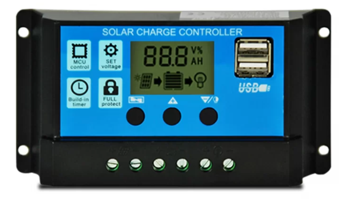
The PWM Solar Charge Controller is a device designed to regulate the voltage and current generated by solar panels to safely charge and maintain batteries. It ensures optimal charging efficiency while protecting the battery from overcharging, deep discharge, and reverse current flow. This controller uses Pulse Width Modulation (PWM) technology to maintain the battery at its optimal charge level.
Explore Projects Built with Solar Charge Controller
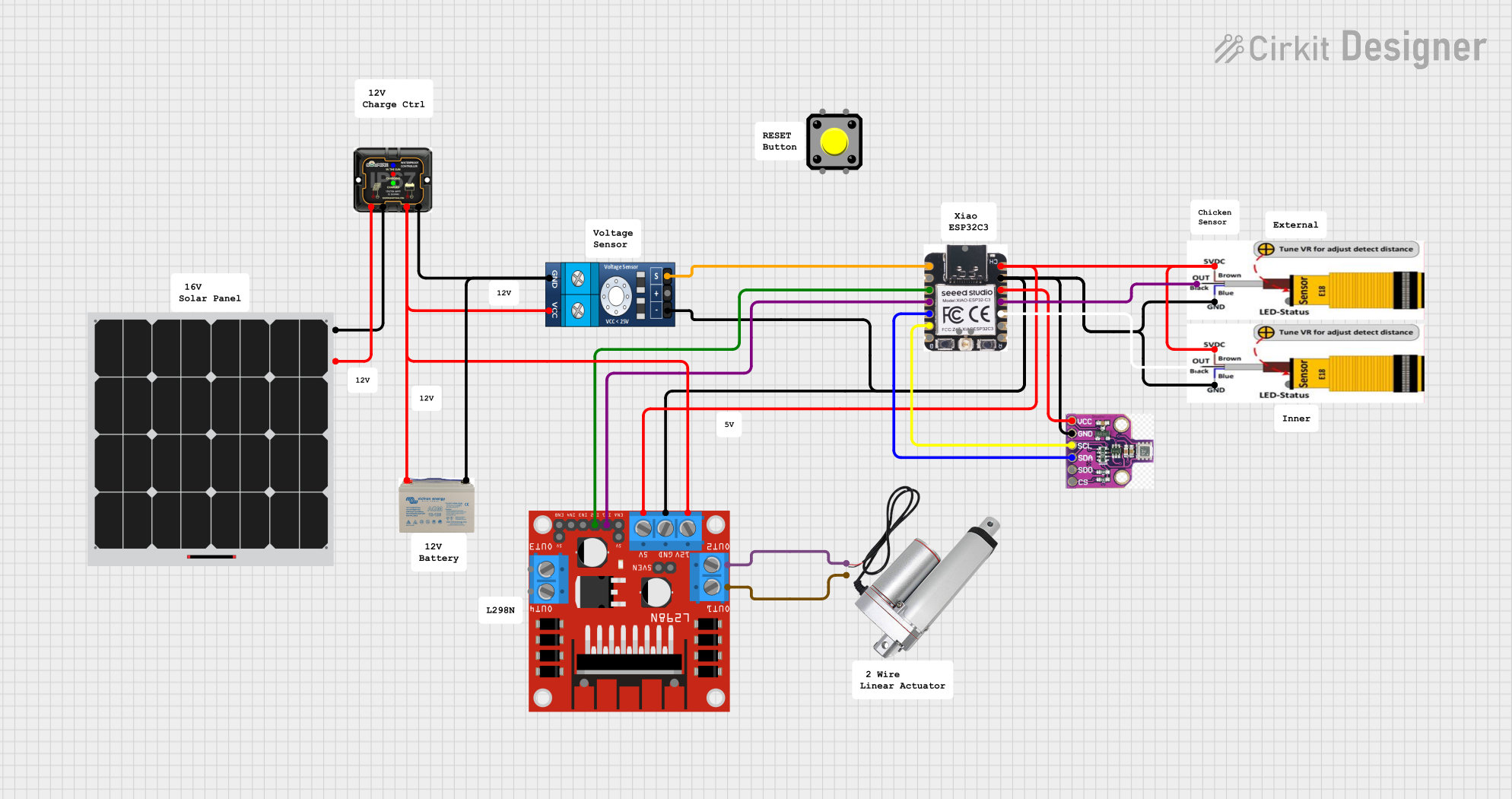
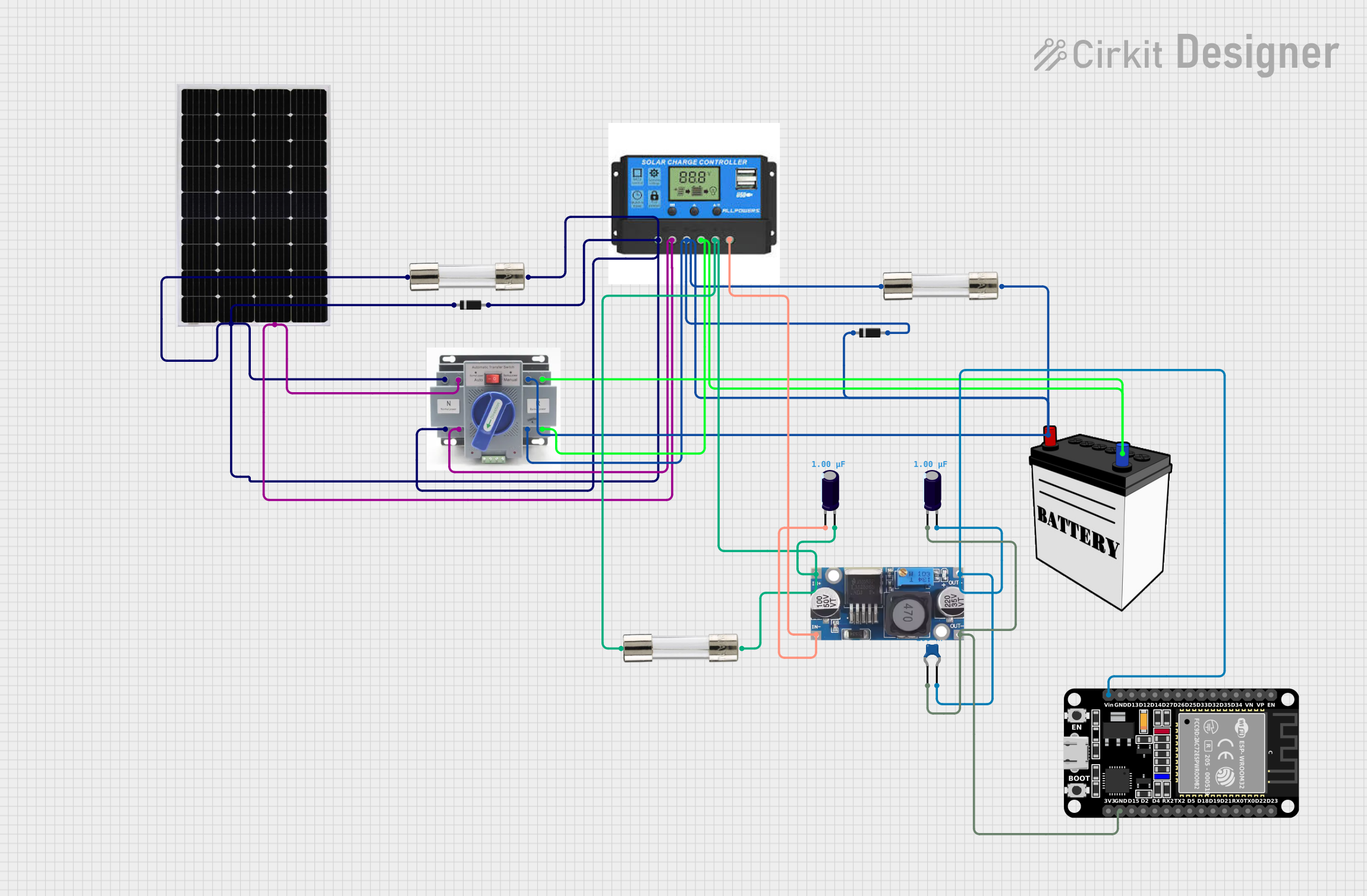
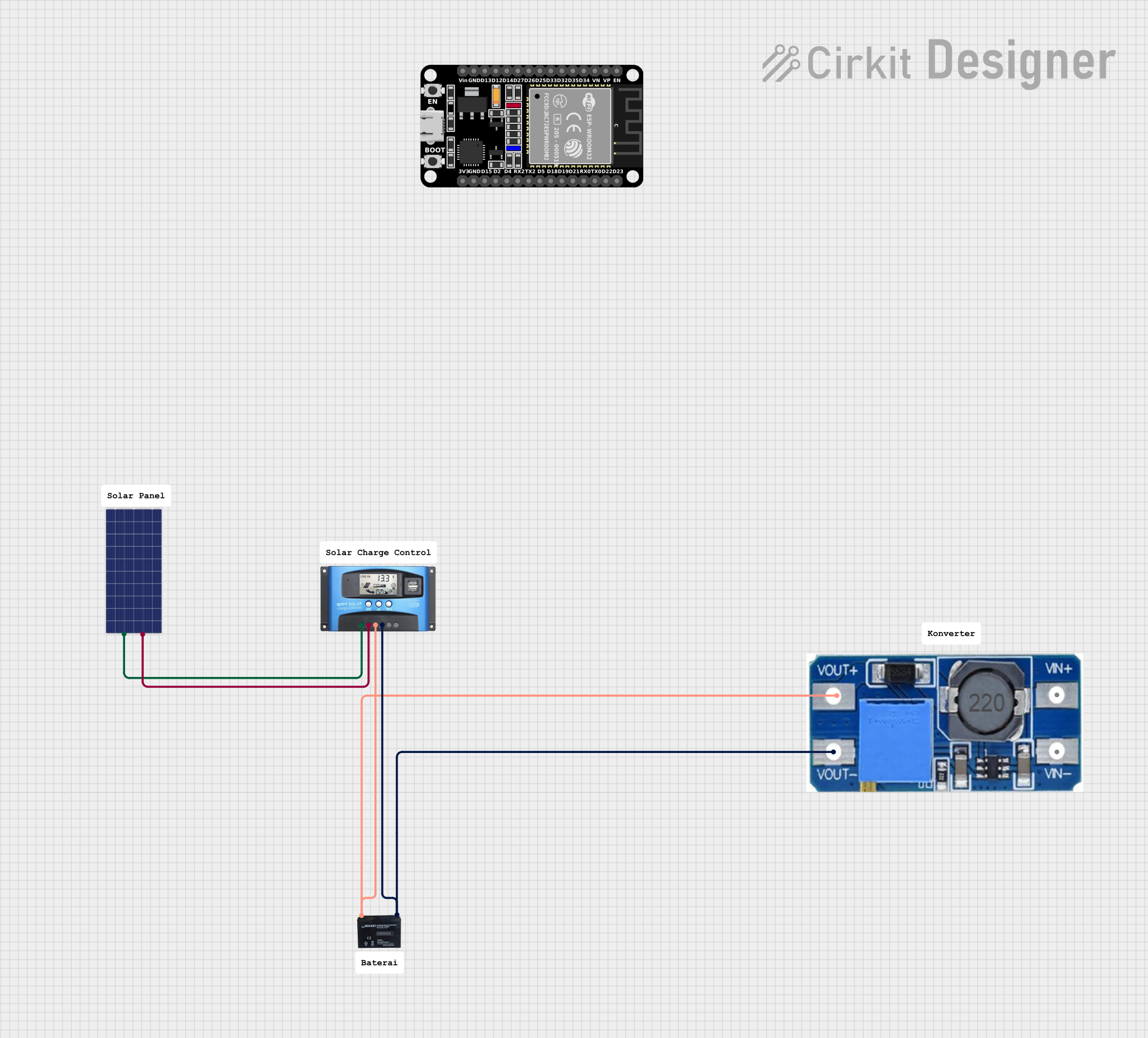
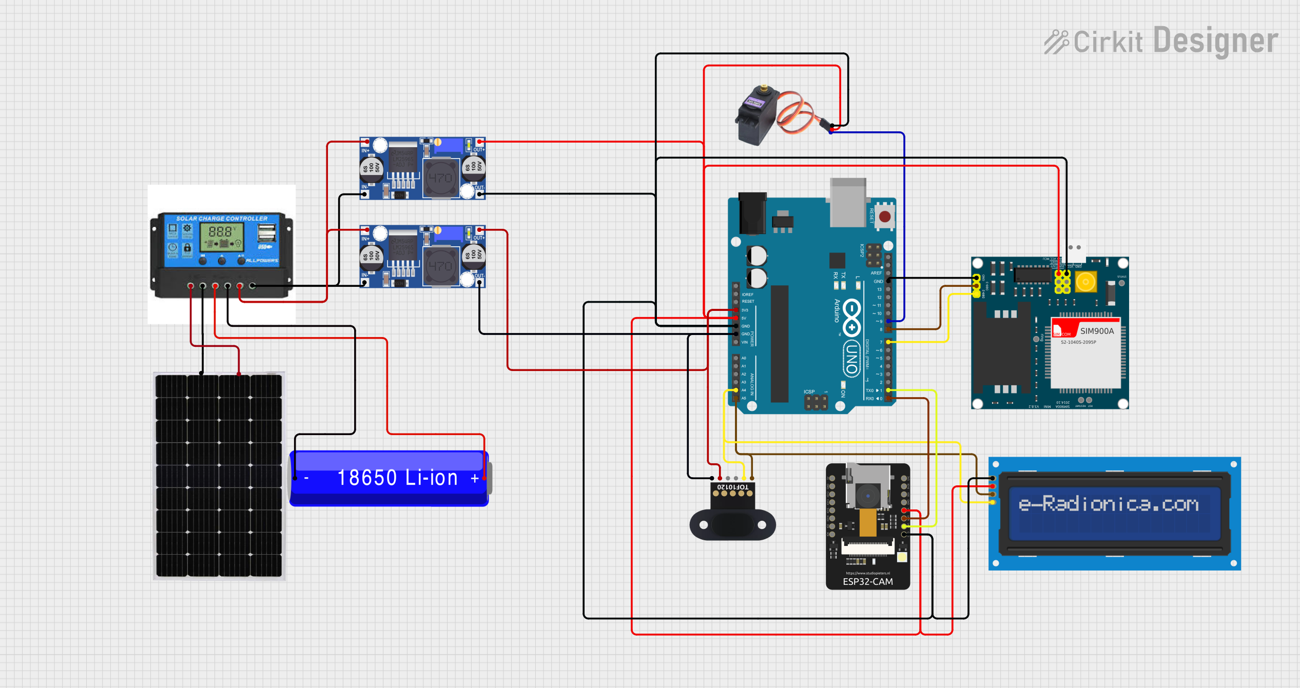
Explore Projects Built with Solar Charge Controller
Common Applications and Use Cases
- Off-grid solar power systems
- Solar-powered lighting systems
- RVs, boats, and caravans with solar setups
- Backup power systems with solar energy
- Small-scale renewable energy projects
Technical Specifications
Below are the key technical details for the PWM Solar Charge Controller:
| Parameter | Value |
|---|---|
| Manufacturer | PWM |
| Part ID | PWM |
| Input Voltage Range | 12V/24V auto-detect |
| Maximum Input Current | 10A, 20A, or 30A (model-specific) |
| Battery Voltage Range | 12V/24V |
| Charging Technology | Pulse Width Modulation (PWM) |
| Operating Temperature | -20°C to +50°C |
| Efficiency | ≥ 98% |
| Self-Consumption | ≤ 10mA |
| Protection Features | Overcharge, over-discharge, |
| reverse polarity, short circuit |
Pin Configuration and Descriptions
The PWM Solar Charge Controller typically has the following terminal connections:
| Pin/Terminal | Label | Description |
|---|---|---|
| 1 | Solar Panel (+) | Positive terminal for connecting the solar panel |
| 2 | Solar Panel (-) | Negative terminal for connecting the solar panel |
| 3 | Battery (+) | Positive terminal for connecting the battery |
| 4 | Battery (-) | Negative terminal for connecting the battery |
| 5 | Load (+) | Positive terminal for connecting the DC load (e.g., lights, fans) |
| 6 | Load (-) | Negative terminal for connecting the DC load |
Usage Instructions
How to Use the Component in a Circuit
- Connect the Battery: Always connect the battery to the charge controller first. Match the positive (+) and negative (-) terminals of the battery to the corresponding terminals on the controller.
- Connect the Solar Panel: After the battery is connected, attach the solar panel to the controller. Ensure the polarity is correct.
- Connect the Load (Optional): If you are powering a DC load, connect it to the load terminals on the controller.
- Power On: Once all connections are secure, the controller will automatically detect the system voltage (12V or 24V) and begin operation.
Important Considerations and Best Practices
- Battery First: Always connect the battery before the solar panel to avoid damaging the controller.
- Correct Polarity: Double-check all connections to ensure the correct polarity. Reversed connections can damage the controller.
- Avoid Overloading: Ensure the connected load does not exceed the controller's rated current.
- Ventilation: Install the controller in a well-ventilated area to prevent overheating.
- Regular Maintenance: Periodically check the connections and clean the terminals to ensure optimal performance.
Example: Connecting to an Arduino UNO
While the PWM Solar Charge Controller is not directly programmable, it can be used in conjunction with an Arduino UNO to monitor battery voltage or solar panel performance. Below is an example code snippet to read the battery voltage using an Arduino:
// Example: Reading battery voltage from a PWM Solar Charge Controller
// Connect the battery (+) terminal to an analog pin on the Arduino via a voltage divider

const int batteryPin = A0; // Analog pin connected to the battery voltage divider
const float voltageDividerRatio = 5.7; // Adjust based on your resistor values

void setup() {
  Serial.begin(9600); // Initialize serial communication
}

void loop() {
  int rawValue = analogRead(batteryPin); // Read the analog value
  float batteryVoltage = (rawValue * 5.0 / 1023.0) * voltageDividerRatio;

  // Print the battery voltage to the Serial Monitor
  Serial.print("Battery Voltage: ");
  Serial.print(batteryVoltage);
  Serial.println(" V");

  delay(1000); // Wait for 1 second before the next reading
}
Note: Use a voltage divider circuit to step down the battery voltage to a safe range (0-5V) for the Arduino's analog input pins.
Troubleshooting and FAQs
Common Issues and Solutions
| Issue | Possible Cause | Solution |
|---|---|---|
| Controller does not power on | Battery not connected or low voltage | Ensure the battery is properly connected and has sufficient charge. |
| Solar panel not charging the battery | Incorrect wiring or insufficient sunlight | Check the solar panel connections and ensure it is exposed to direct sunlight. |
| Load not receiving power | Load exceeds controller's rated current | Reduce the load or use a higher-rated charge controller. |
| Overheating | Poor ventilation or high ambient temperature | Install the controller in a well-ventilated area away from direct sunlight. |
| Battery overcharging or undercharging | Incorrect system voltage detection | Verify the battery voltage and ensure the controller is set to the correct mode. |
FAQs
Can I use this controller with a lithium-ion battery?
- Yes, but ensure the controller supports lithium-ion batteries and configure the settings accordingly.
What happens if I connect the solar panel before the battery?
- This can damage the controller. Always connect the battery first.
Can I use this controller for a 48V system?
- No, this controller is designed for 12V/24V systems only.
How do I know if the battery is fully charged?
- Most controllers have an LED indicator or display that shows the battery's charge status.
By following this documentation, you can safely and effectively use the PWM Solar Charge Controller in your solar power system.